Coopra Advanced Heating Technologies Installation manual E40C
11
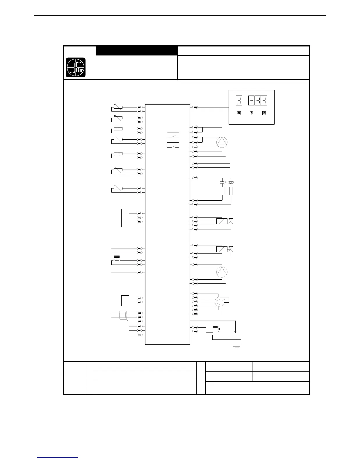
1.6. Connection diagram (general)
-T
-T
-T
-T
-T
Outside temp
(S4)
Inlet temp
(S2)
DHW temp
(S3)
Outlet temp
(S1)
Tank temp
(S6)
Flue temp
(S5)
0÷10 V input
OpenTherm
L
N
PE
RS 485
Twin / Zone
BURNER
IO
Fan
Pump 2
Gas valve
BIC 0.585.303
MMI 0.585.503
CN11-2
CN12-4
CN12-3
CN11-1
CN12-5
CN11-3
CN12-6
CN11--9
CN12-10
CN12-9
CN11-8
CN12-11
CN11-13
CN11-6
CN11-7
CN11-10
CN11-14
CN4-1
CN5-1
CN5-2
CN12-12
CN7
CN10-18
CN10-9
CN5-10
CN5-9
CN1-7
CN1-6
CN5-5
CN2-5
CN2-3
CN2-2
CN2-4
CN5-6
CN8
L2
V-
V+
L1
+
Group CONNECTION DIAGRAM
S.I.T.
Controls B.V.
SIT
091110
A
EV
Type :
BIC-0.585.303
New Revision board 303
07-05-10 EV
1:1 n.a.
DAT E : DR AWN :
SCALE : UN IT :
COPYRIGH T ACC ORD ING TO L AW
FIL E : PAG E :
058 5 303_A S E.mk d
Pump PWM
HSI
CN2-1
Hall
CN4-2
PE
CN4-4
CN4-5
Safety limit thermostat
(S7)
CN10-1
CN10-10
PC connection
CN15
Three way valve
CN1-2
CN1-3
CN4-3
CN1-1
PE
L''
N
L'
Pump H/L
*CN3-6
*CN3-4
*CN3-5
*CN3-3
CN1-4
CN1-5
CN4-6
PWM
GND
GND
CN14-1
CN14-3
Indication
24 V
CN14-2
Alarm
Running
L'
L', high
L', low
N
PE
L'
L'
*) simultaneous activation of both relays must be avoided
L'
N
PE
N'
PE
CN11-12
GND
A
B
GND
CN12-2
CN12-1
CN12-7
Water pressure sensor
GND
in
24 V
100115
B
EV
Water pressure switch replaced by sensor
Optional
(S7)
CN11-5
CN11-12
100507
C
EV
Optional sensor (S7) added
 Loading...