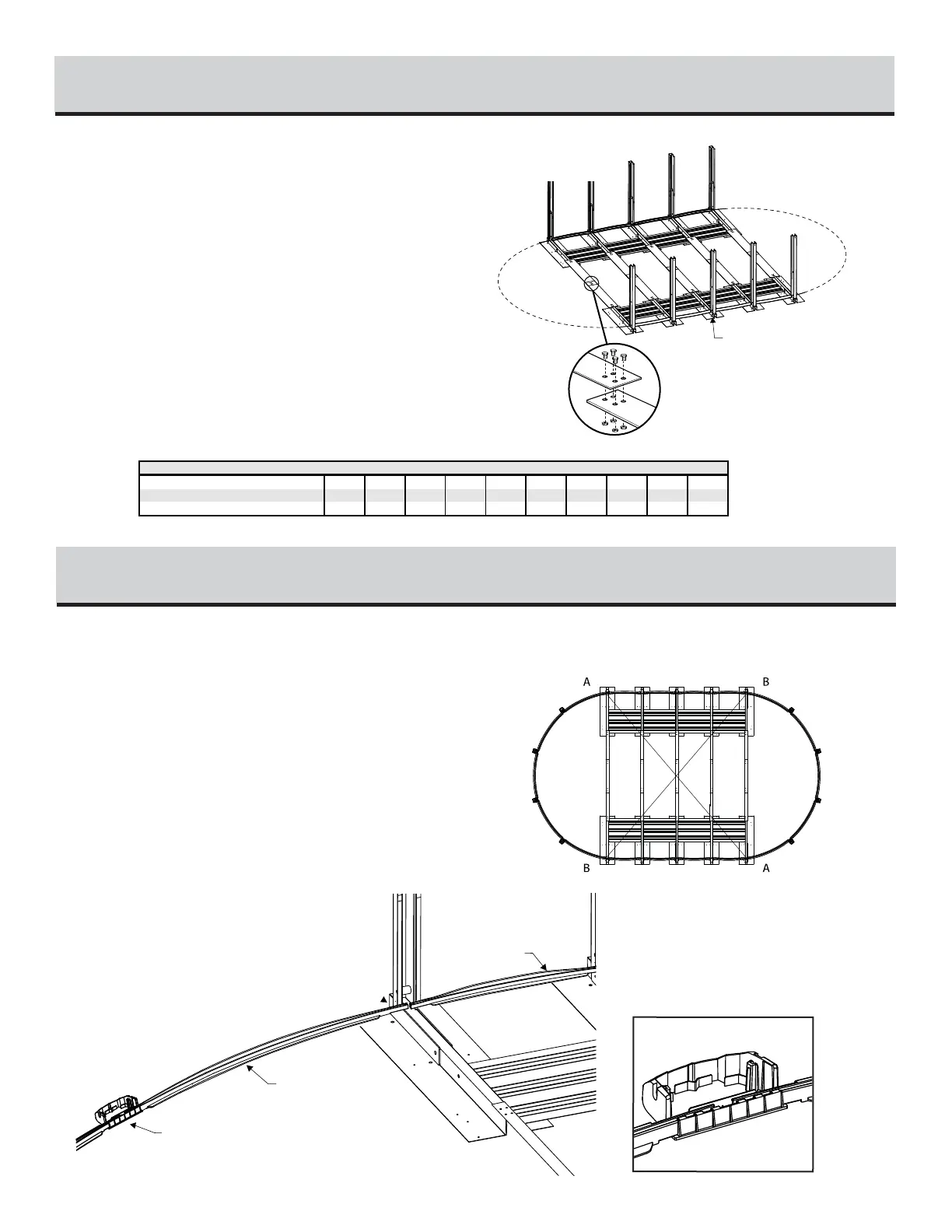
1) Study illustrations and chart carefully. You are now ready to as-
semble the metallic tension straps. Refer to indications on the chart
for the exact number of tension straps and sections per straps ac-
cording to their respective pool size.
2) Refer to Illustration 6.1: If there is more than one metallic
strap per tension strap rows, assemble the straps together using 4
bolts and nuts (BB) 1/4" #20 X 5/8" (6,35 mm X 15,88 mm), tak-
ing care of placing the bolt head on top.
3) Attach the assembled tension straps to foot beams on both sides,
using 4 standard screws #14.
TENSION STRAPS ASSEMLBY
6
Start with round section, refer to illustration 7.1 :
Place the end of the first round section bottom track on the foot
beam of the last pillar of the straight section. At the other end, place
the first foot plate of the round section.
Round section, refer to Illustration 7.2 :
Using the round section bottom tracks and the foot plates, start with
the first plate of the round section. Repeat this procedure until the
half circle is completed.
Refer to Illustration 7.3. :
Before going to next step, make sure that the centre of the pool is
properly squared and metallic tension straps are stretched.
ROUND SECTION BOTTOM TRACKS ASSEMBLY
7