2
44
45
36
43
42
38
39
47
46
48
37
41
49
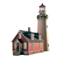
Lighthouse Tower Assembly
1) Note the correct placement and glue Window
Glass (46, 47, 48) inside Tower (37). Insert Lower
Door (41) to Tower.
2) Insert Gallery Deck (38) to top of Tower.
3) Insert Door (42) to Service Room (39). Insert
Service Room assembly to top of Tower.
4) Insert Lantern Room Base (43) to top of Service
Room. Insert Lens (36) to top of Lantern Room Base.
Insert Roof (45) to top of Lens. Insert Vent Ball (44)
to opening in top of Roof.
BROWN
YELLOW
10 – 16 V AC ~
14 – 24 V DC =
13 – 24 V Digital signal
NOTE: Before connecting the lighting circuit, check that the output voltage of the
ACCESSORY terminals on your power pack or other power source does not
exceed 14V AC.
Carefully wrap the bare wire at the end of the brown lead around one of the
ACCESSORY terminals on your power pack and tighten; repeat for the yellow wire
on the other terminal. Be sure the wires do not touch each other or more than one
terminal.
Note that the longer lead on the LED is the positive (anode) lead; insert the LED to
the black (negative/ground) and red (positive/power) lead as shown.
(-)
(+)
40
21
20
15
1
Attaching to Base
1) Insert completed Tower to opening at rear of Base (1)
2) Insert Front Wall (3) to Base (1). Insert Side Walls (2x 2) to Base and
inside corners of Front Wall. Insert Rear Wall (4) to Base and inside
corners of Side Walls.