corsair.com/link
Installation Instructions
1. Power o your system for the installation of the
Corsair Commander Mini.
2. The Corsair Commander Mini can be mounted in many
empty locations inside your case for ease of cable
routing. Its slim design allows for installation on the
rear of the motherboard tray in most cases. Its width
also allows for internal mounting in the optical disk
drive cage of most cases. We recommend making all
of the required connections first, and then attaching
the Commander Mini to your PC case. Use the
provided mounting tape to secure the Commander
Mini unit to your PC case.
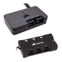
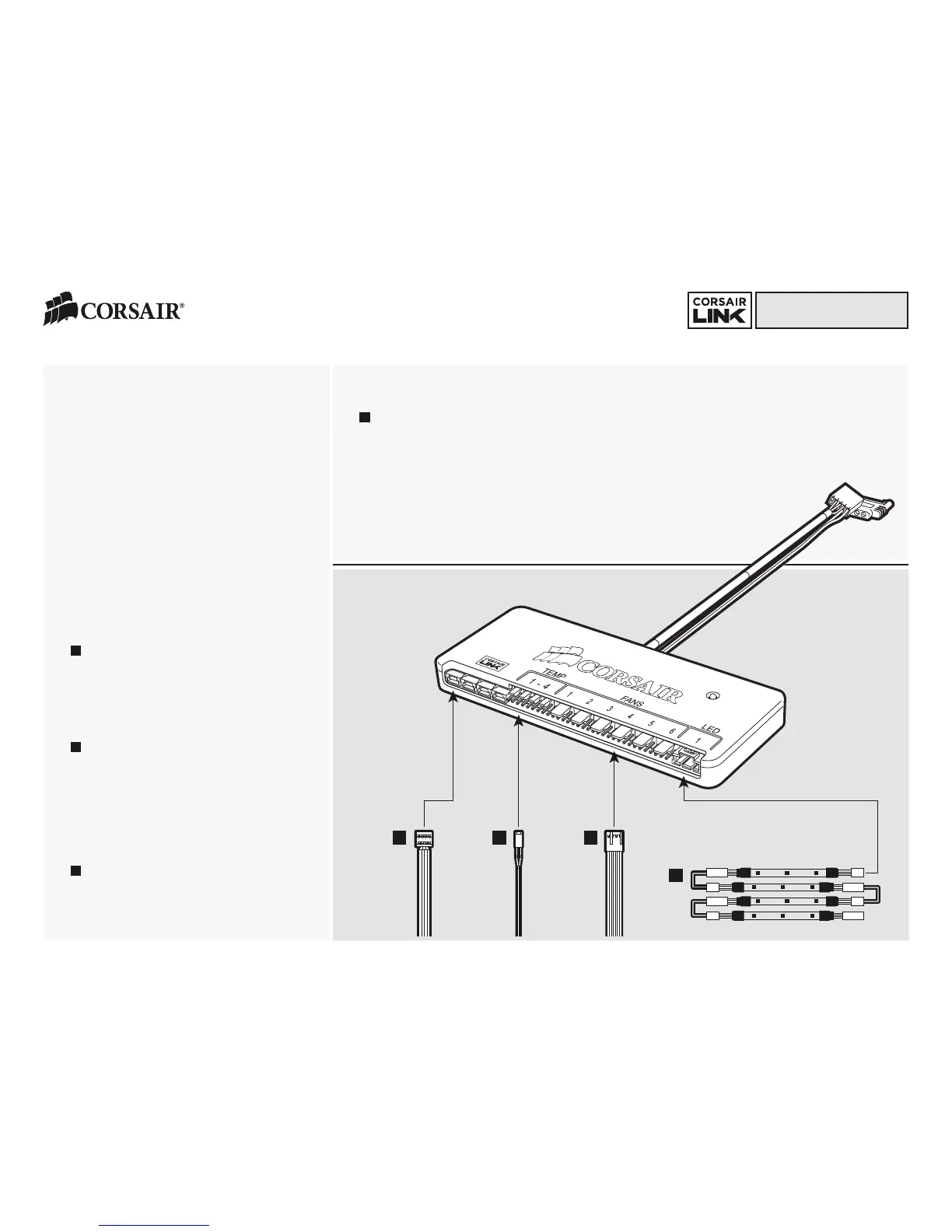
3. Connect the attached USB cable to any available
internal USB 2.0 header on your PC’s motherboard
(Refer to your motherboards manual for location).
Take care when connecting the USB cable, as it is
keyed to prevent incorrect installation.
4. Connect the attached SATA power connector to any
available SATA connector from your power supply.
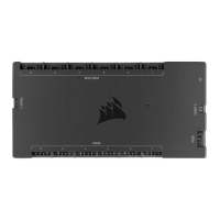
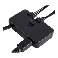
5. The Corsair Commander Mini has 4 Corsair Link
Digital ports that are for connecting to other Corsair
Link Digital hardware. Use the provided Corsair Link
Digital cable to connect to an H80i or H100i. To
connect to a Corsair PSU with Corsair Link Digital
capabilities (I Series) use the cable supplied with the
power supply to connect to the ports on the
Commander Mini.
6. Connect the thermal sensors to the two-pin
headers labeled “Temp 1-4” on the Commander Mini.
Tips for connecting thermal sensors
The thermal sensors are designed to measure ambient
temperatures, so for the most accurate results, they
should not directly touch components. You may find it
useful to mount the thermal sensors near air intake and
exhaust points, and if your PC case has multiple
compartments, you can try placing each of the sensors
in its own compartment. Since the thermal sensors can
easily repositioned, you can try various locations and
use what works best for you.
7. Connect any fans you wish to control to the four
pin headers labeled “Fans 1-6”. The included fan
extension cables can be used if necessary.
8. Connect the RGB LED strips (sold separately) to the
connectors labeled “LED 1”.
9. Hardware installation is complete.
10. Download the Corsair Link Dashboard software
11. The software can be downloaded from the following
location: www.corsair.com/linksw
12. Install the Corsair Link Software
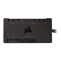
The LED on the Corsair Commander Mini shows activity and
status. Green indicates USB connectivity with the host PC.
Amber (intermittent) indicates USB activity. Red indicates
USB connectivity error.
[Optional]
a
a
b
c
d
b
c
d
 Loading...