9 10
ENGLISH
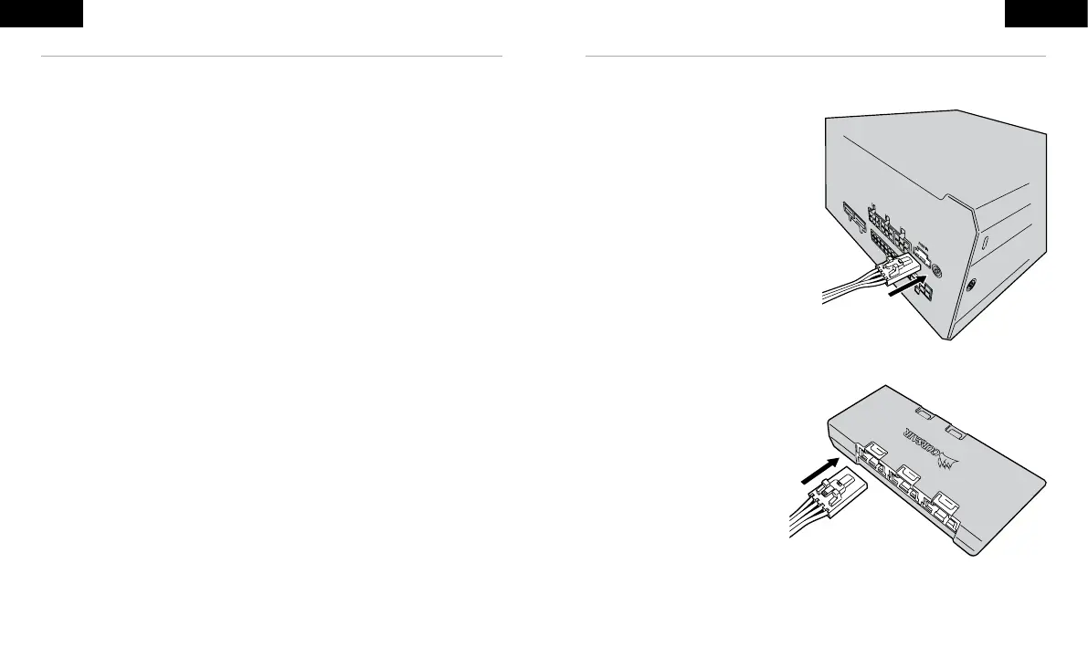
CONTROLLING THE RGB FAN IN YOUR NEW PSU
For iCUE control
1. Plug iCUE RGB cable into the PSU.
2. Plug other end of cable into a compatible
CORSAIR RGB Lighting Controller’s
(Commander PRO or Lighting Node PRO) 6-port
RGB hub.
3. Select SP RGB PRO/CX-F Series PSU in the
Lighting Setup tab.
Note: The 6-port hub requires devices to be plugged
in sequentially, and all fans plugged into the hub
must be of the same type or you may experience
lighting issues.
Download iCUE at:
www.corsair.com/downloads
The CX-F has the ability to be controlled by
CORSAIR’s iCUE software, through a compatible
motherboard’s +5V ARGB header, or manually using
the RGB button on the PSU.
Note: Before plugging or unplugging the RGB cable,
please ensure your computer is shut down and the
power switch on the back of the PSU is turned to the
“off” position.
ENGLISH
INSTALLING YOUR NEW CX-F RGB SERIES POWER SUPPLY
Step 1: Removing your existing PSU
If you are building a new system, skip to Step 2.
1. Disconnect the AC power cord from your wall outlet or UPS and from the existing power supply.
2. Disconnect all the power cables from your video card, motherboard and all other peripherals.
3. Follow the directions in your chassis manual and uninstall your existing PSU.
4. Proceed to Step 2.
Step 2: Installing the new power supply
1. Make sure the power supply’s AC power cable is not connected.
2. Follow the directions in your chassis manual and install the power supply with the screws provided.
3. Connect the 24-pin (ATX) cable to the motherboard. Connect the eight-pin +12V (EPS12V) cable to
the motherboard.
a. If your motherboard has an eight-pin +12V socket, connect the eight-pin cable
directly to your motherboard.
b. If your motherboard has a four-pin socket, detach the four-pin from the eight-pin cable,
and then plug this four-pin cable directly to your motherboard.
c. Some motherboards will require a mix of 8+4 pins, use as many EPS12V cables as
necessary and do not mistake them for PCIe cables.
4. Connect the peripheral cables, PCI-Express cables, and SATA cables.
a. Connect the SATA cables to your SATA SSD or hard drive’s power sockets.
b. Connect the PCI-Express cables to the power sockets of your PCI-Express video cards
if required.
c. Connect the peripheral cables to any peripherals requiring a 4-pin connector.
d. Make sure all the cables are tightly connected. Be sure to save any unused modular
cables for future component additions.
5. Connect the AC power cord to the power supply and turn it on by pushing the switch to the ON position
(marked with “I”).
 Loading...