COR-ACC980
V150921
M4/M8
M4/M6/M8
M4/M6/M8
M4/M8
M4/M8
M4/M6/M8
M4/M6/M8
Relay time of lift controller setting
Factory setting-2 (Function default value)
Real time clock setting (Stand-Alone)
Anti-pass-back (Enable user)
Lift control setting: single door
Force open alarm setting
Delete all tag
Function Default Value
Option 0= none value; Option 1= 1 x each value
(i.e. DDD value of Enable “Auto Open” + ”Exit by Push Button +”Anti-pass-back”
=004+016+128=148; As a result of that, the command will be 20 148 .)
24 DDD
Function Option Value Application
※
Default Value
Auto-open door without
presenting card at auto
open zone
Alarm Output/Lift Control
Stop Alarm by…
Door bell
※
0: Disable
※
0: Alarm Output
0: None
※
0: Disable
Networking/Stand-Alone
Networking/Stand-Alone
Networking/Stand-Alone
Networking/Stand-Alone
001
002
064
128
1: Enable
1: Lift Control
※
1: Push Button/
Door Closed
1: Enable
20 DDD
Function Option Value Application
※
Default Value
Time Attendance
Auto Re-lock
Auto Open
Exit by Push Button
Master Reader of Network
Access/Exit Reader
Anti-pass-back
※
0: Yes
※
0: Disable
※
0: Disable
0: Disable
※
0: Slave
※
0: Exit
※
0: Disable
Networking
Networking/Stand-Alone
Networking/Stand-Alone
Networking/Stand-Alone
Networking
Networking
Networking
001
002
004
016
032
064
128
1: No
1: Enable
1: Enable
※
1: Enable
1: Mater
1: Access
1: Enable
23 NNN TTT
24 DDD
25 YYMMDDHHmmss
26 SSSSS EEEEE N
27 UUUUU FF
28 NNN
29 29
NNN=Node ID of lift controller, TTT= relay time: 000~600=1~600 sec.
Please refer to function default value for details.
YYMMDDHHmmss: Year/ Month/ Day/ Hour/ Min./ Sec.
SSSSS=Starting user address; EEEEE=Ending user address;
N=0/Enable; N=1/Disable; N=2/Initial
UUUUU=User Address; FF=Floor number (01~32 oor/stop)
Please refer to function default value for details.
28 NNN
Function Option Value Application
※
Default Value
Dual Door Open
Force Open
Alarm Output
※
0: Disable
※
0: Disable
Networking/Stand-Alone
Networking/Stand-Alone
064
128
1: Enable
1: Enable
Adding and Deleting Tag
Mode4/Mode8
Adding the Single Tag or the Random tags
[i.e.] User Address NO.100 and NO.101 have 2 pcs of random tags:
Access programming mode
→
19 00100 00001
→
Close Tag into RF Area
→
OK
P.S. The First tag has now been added, present the rest of the tags one after the other to add them to the system as well.
Input 123456 (or Master Code)
→
19 UUUUU 00001
→
Close Tag into RF Area (Present the tag to the controller.)
→
OK (Memory location number)
Adding the Sequential tags
[i.e.] User Address NO.101 to NO.120 have 20 pcs of sequential tags:(62312~62332)
:
Access programming mode
→
19 00101 00120
→
Close Tag into RF Area(only use the tag NO.62312)
→
OK
Input 123456 (or Master Code)
→
19 UUUUU QQQQQ
→
Close Tag into RF Area (Present the tag with the lowest number to the controller.)
→
OK (Memory location number)
Deleting All Tags
Input 123456 (or Master Code)
→
29 29
Deleting the Single Tag
Input 123456 (or Master Code)
→
10 SSSSS EEEEE
9
[i.e.] Delete User Address: 00058
Access programming mode
→
10 00058 00058
9
Deleting a batch of Tags
Input 123456 (or Master Code)
→
10 SSSSS EEEEE
9
[i.e.] Delete User Address: 00101~00245
Access programming mode
→
10 00101 00245
9
Mode6
※
At the Mode 6, User Address = Card Code
Adding Tag
[i.e.] Add User Address: 00100~01254
Access programming mode
→
11 00100 01254
→
OK
Input 123456 (or Master Code)
→
11 SSSSS EEEEE
→
OK
Deleting Tag
[i.e.] Delete a tag with card code 62362
Access programming mode
→
10 62362 62362
→
OK
Input 123456 (or Master Code)
→
10 SSSSS EEEEE
→
OK
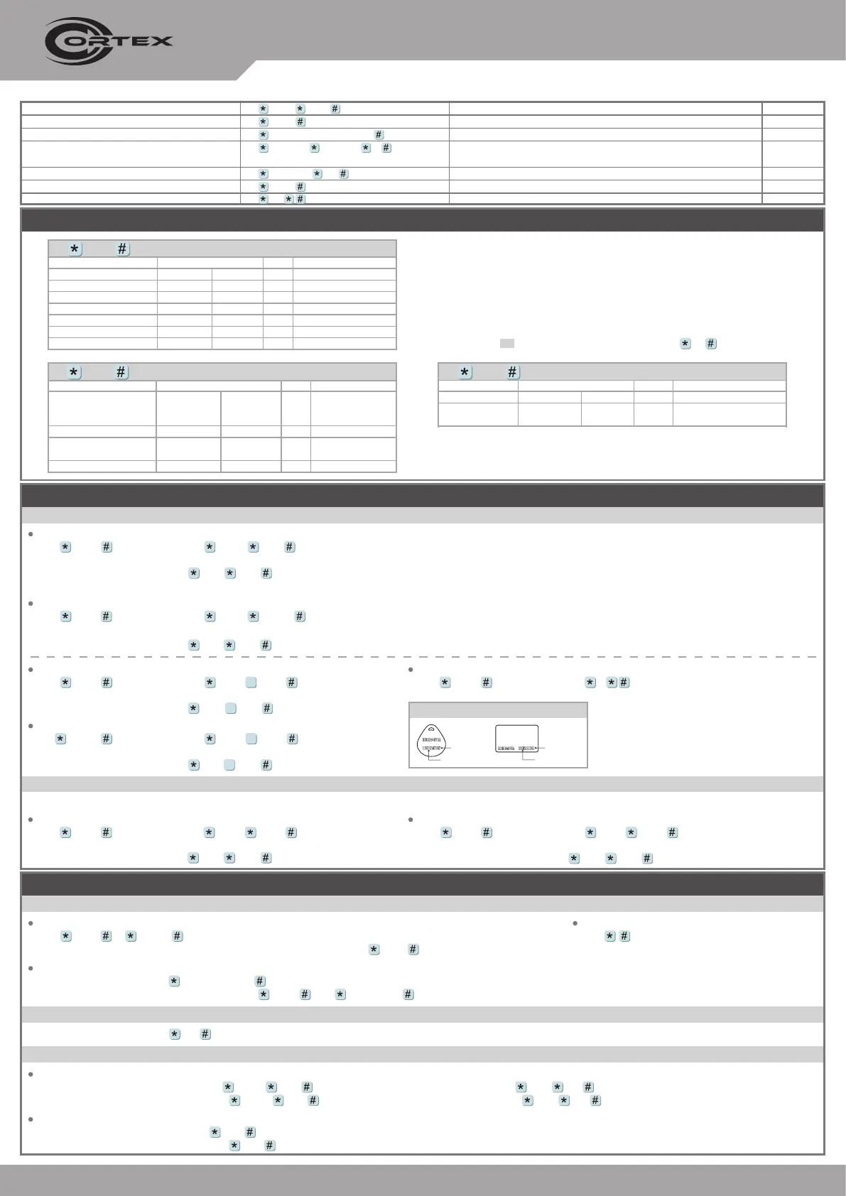
Tag Information
SITE CODE
CARD CODE
SITE CODE
CARD CODE
Programming
Entering
[i.e.] The Default Value= 123456, if already changed the Master Code= 876112, input
876112
→
Access programming mode
Input 123456 or PPPPPP
Changing the Master Code
[i.e.] If want to changing the Master Code= 876112, input
123456
→
09 876112876112
Access programming mode
→
09 PPPPPPRRRRRR [Input the 6-digit new master code twice.]
Exiting
Input
A. Entering and Exiting Programming Mode
Access programming mode
→
00 NNN [Node ID: 001~254]
B. Changing the Node ID of Reader
Individual PWD (M4/M8)
Card or PIN:
Access programming mode
→
12 UUUUU PPPP [i.e. User address: 00001 and PWD: 1234, input 12 00001 1234 ]
Card and PIN:
Access programming mode
→
13 UUUUU PPPP [i.e. User address: 00001 and PWD: 1234, input 13 00001 1234 ]
Public PWD (M6)
PIN only:
Access programming mode
→
15 PPPP [Input 4-digit PWD, default value: 4321]
Card and PIN:
Access programming mode
→
17 PPPP [Input 4-digit PWD, default value: 1234]
C. Setting up the password
 Loading...