2
B 268 - XSE 602 C1 Eng. 22.11.10 AM REV. 02
We reserve the right to make changes witout notice
COSTER
4. TECHNICAL DATA
• Electrical
Power supply 230 V AC ± 10%
or 240 V AC for UK market
Frequency 50 … 60 Hz
Consumption 5 VA
Protection IP40
Radio disturbances VDE0875/0871
Vibration test with 2g (DIN 40 046)
Voltage-free output contacts:
maximum switching voltage 250 V ~
maximum switching current 5 (1) A
Construction standards Italian Electrotec. Committee (CEI)
Data storage 5 years
• Mechanical
Case DIN 6E module
Mounting DIN 35 rail
Materials:
base NYLON
cover ABS
Ambient temperature:
operation 0 … 45°C
storage – 25 … + 60°C
Ambient humidity Class F DIN 40040
Dimensions 105 x 115 x 71,5
Weight 1.0 kg
• Programmes & periods
24-hour programmes
1 … 25
24-hour events
2 … 6
7-day programmes 0 … 2
Holiday periods
0 … 25
Special period 1
Remote Extension period 0 ...
3 ... 72 h
• Measurement ranges
Flow temperature 0 … 99 °C
Outside temperature – 30 … + 40 °C
Ambient temperature 0 … 30 °C
Anticondensing temperature 0 ... 99 °C
• Heating
Flow temperature:
radiators 40 ... 70 ... 99 °C
fan coil 40 ... 80 ... 99 °C
panels 20 ... 40 ... 50 °C
minimum limit
1 … 99 °C
maximum limit 1 … 99 °C
Design outside temperature – 30 … – 5 … + 20 °C
Correction curve origin 20 … 40 °C
Boiler anticondensing temp. 0 ... 50 ... 99 °C
Delay switching off pump 2 ... 30 ... 60 minutes
Ambient Authority
0 ... 20 °C/°C
Mode temperatures :
ambient 5 Normal 0 … 19-21 … 30 °C
ambient 2 Setback 0 … 14-16 … 30 °C
ambient Frostprot 0 … 6.0 … 30 °C
ambient Remote Extension 0 … 21.0 … 30 °C
water 2 Flows 0 … 20-30 … 99 °C
Valve actuator run time 30...630...3,600 s
Optimisation of operating times:
start inertia 0.00 ... 1.00 ... 7.45 h
limit “Normal” optimisation 0.00 ... 2.00 ... 12.00 h
limit “Holidays” optimisation 0.00 ... 10.00 ... 40.00 h
boosting 0.0 ... 3.0 ... 10.0 °C
reduction ambient temp. optimum stop 0.00 ... 0.5 ... 3.5 °C
time constant 1 ... 48 ... 255 h
• Telemanagement
Speed C-Bus chosen from 1200, 2400, 4800, 9600 bauds
• Telemanagement (setting by PC)
Attempts send alarms 1 …
5 … 255
Interval between attempts 2 … 10 … 255 min.
Alarms (setting by PC):
threshold diff. flow 1 temperature (B1) 0.5…
5…99 °C
delay diff. flow 1 temperature 2…30…255 min.
threshold diff. flow 2 temperature (B5) 0.5…
5…99 °C
delay diff. flow 2 temperature 2…30…255 min.
threshold diff. ambient 1 temperature 0,5…
1…30 °C
delay diff. ambient 1 temperature 2…30…255 min.
threshold diff. ambient 2 temperature (B6) 0.5…
1…30 °C
delay diff. ambient 2 temperature 2…30…255 min.
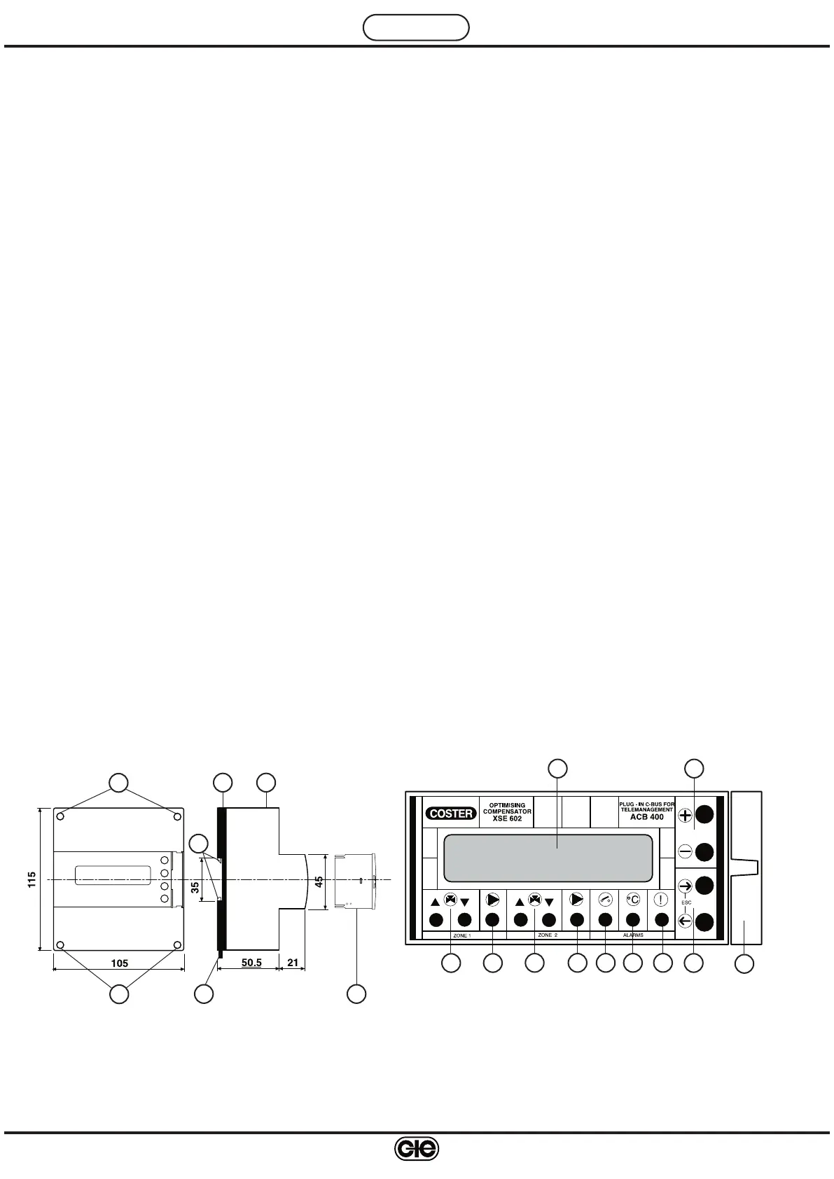
1 - Two-line backlighted alphanumeric display
2 - + and – operating keys
3 -
← and → operating keys
4 - Valve 1 control LEDs
5 - Zone 1 pump control LED
6 - Valve 2 control LEDs
7 - Zone 2 pump control LED
8 - On-Off alarms LED
9 - Measurement alarms LED
10 - Controller fault LED
11 - Plug-in type ACB 400 C1 for C-Bus communication
6. FACIA
1
2
4 5 3
7 8 9 106
WARNING : in presence of electrical disturbances the output controls of the controller may change status but this will be
restored automatically.
5. OVERALL DIMENSIONS
1 – Protective cover for electronic components
2 – Base with transformer, relay & terminal blocks
3 – Screws for fixing cover- base
4 – DIN rail securing elements
5 – DIN rail release lever
6 – Plug-in for C-Bus communication
1
2
3
3
4
5 6
11
 Loading...