2
E 136 - XTA 624 C1 Eng. 22.11.10 AM REV. 02
We reserve the right to make changes without notice
COSTER
4. TECHNICAL DATA (default values in bold print)
• Electrical data
Power supply 24 V ~ ± 10%
Frequency 50 … 60 Hz
Consumption 5 VA
Protection IP40
Radio interference VDE0875/0871
Vibration test with 2g (DIN 40 046)
Voltage-free output contacts:
maximum switching voltage 250 V ~
maximum switching current 5 (1) A
Construction standards Italian Electroth. Committee(CEI)
Data storage period 5 yars
Software Class A
• Mechanical data
Case DIN 6E Module
Mounting DIN 35 rail
Materials:
base NYLON
cover ABS
Room humidity
operating 0 … 45 °C
storage – 25 … + 60 °C
Room humidity Class F DIN 40040
Dimensions 105 x 115 x 71.5
Weight 0.6 kg
• Adjustment ranges
Heating (or cooling) temperatures:
desired room temp. (B3 or B1+B3) 0…20 (25)…40 °C
desired flow temp. (B1) 0…20 (25)…60 °C
min. flow limit (B1+B3) 1…18 (
8)…60 °C
max. flow limit (B1+B3) 1…50 (25)…60 °C
outside default temp. (B1+B2) –30…–10 (35)…40 °C
flow default temp. (B1+B2) 1…50 (10)…60 °C
summer compensation Te–Ta (B2+B3) 0…
6…20 °C
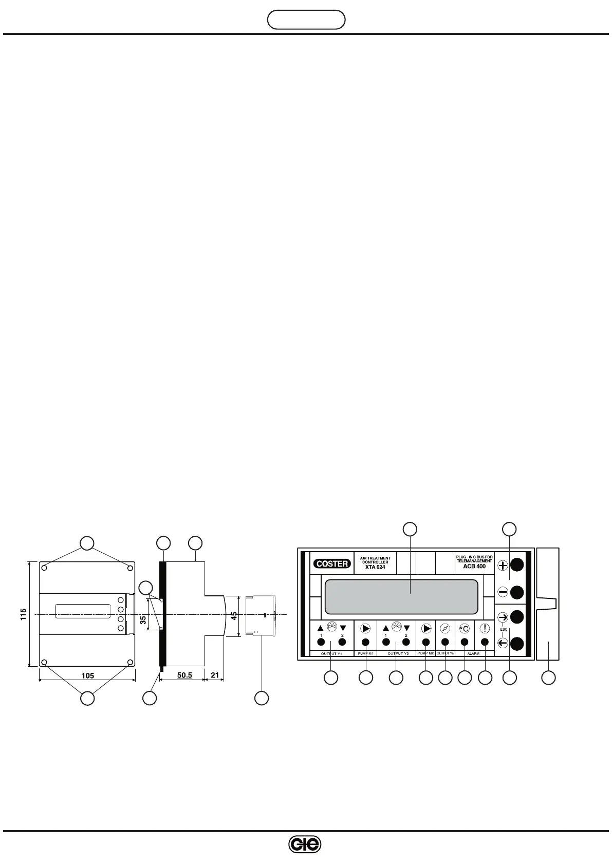
5. OVERALL DIMENSIONS 6. FACIA
1 - Alphanumeric display
2 - + and – operating keys
3 - ← and
→ operating keys
4 - Y1 output LED
5 - M1 pump LED
6 - Y2 output LED
7 - M2 pump LED
8 - Ys output LED
9 - Measurement alarm LED
10 - Microprocessor malfunction LED
11 - Plug-in type ACB 400 C1 for C-Bus communica
-
tion
Preheating temperature (B4) 0…10…40 °C
Temp. proportional band (base value):
Heating (room)(B3 o B1+B3) ±1…±2 …±40 °C
Heating flow (B1) ±1…±10…±40 °C
Various temp. proportional band multipliers:
Heating flow(B1+B3) Bp amb x 0,5…10…20
Cooling temperatures Pb heat x 0,5…20
preheating (B4) Pb heat disch x 0,5…
1…20
Air dampers (B2+B3) Pb room heat x 0,5…
1…20
Valve stroke time (modulating) 0…10…255 min.
Y1, Y2 output control – modulating
– 2 stage
– 3 stage
Valve stroke time (modulating) 30…120…630 s
Ys output control 0…10 V–
Season switching: – manual (display)
– external control
M1, M2 pump Off control delay 0…20…99 min.
• Alarm adjustments
Telemanagement (PC-controlled adjustments)
Alarm call attempts 1…
5…255
Alarm call interval 2…10…255 m
Alarms (PC-controlled adjustments):
Disch.temp. diff. threshold (B1) 1…
5…99
°C
Disch.temp. diff. delay 2…30…255 min.
Room temp. diff. threshold (B3) 0,5…
1…30 °C
Room temp. diff. delay 2…30…255 min.
Preheat temp. diff. threshold (B4) 1…
5…99 °C
Preheat temp. diff. delay (B4) 2…
5…255 min.
• Telemanagement
Speed C-Bus chosen from 1200, 2400, 4800, 9600 bauds
Warning :
In case of static, the equipment’s output controls may change
settings; original settings will be subsequently restored auto
-
matically.
1
2
4
5
6 37 8 10
9
1 – Protective cover for electronic components
2 – Base with transformer, relay & terminal blocks
3 – Screws for fixing cover- base
4 – DIN rail securing elements
5 – DIN rail release lever
6 – Plug-in for C-Bus communication
1
2
3
3
4
5 6
11
 Loading...