3
E 136 - XTA 624 C1 Eng.
22.11.10 AM REV. 02
We reserve the right to make changes without notice
COSTER
Ss Win and c1 closed = On - Winter;
ss Sum and c1 open = On – Summer
c1 open = Off
Season switching (M2.
2) must be:
through ss control
c1 closed = On; c1 open = Off
Possible Season switching (M2.
2) modes:
No ; Winter ; Summer ; Based on Outside Temp.;
Based on Room Temp.; Based on Seasons
Always On (as supplied)
Possible Season switching (M2.
2)modes:
No ; Winter; Summer; Based on Outside Temp.;
Based on Room Temp.; Based on Seasons
ss Win = On – Winter
ss Sum = On – Summer
Season switching(M2.
2) must be:
through ss control
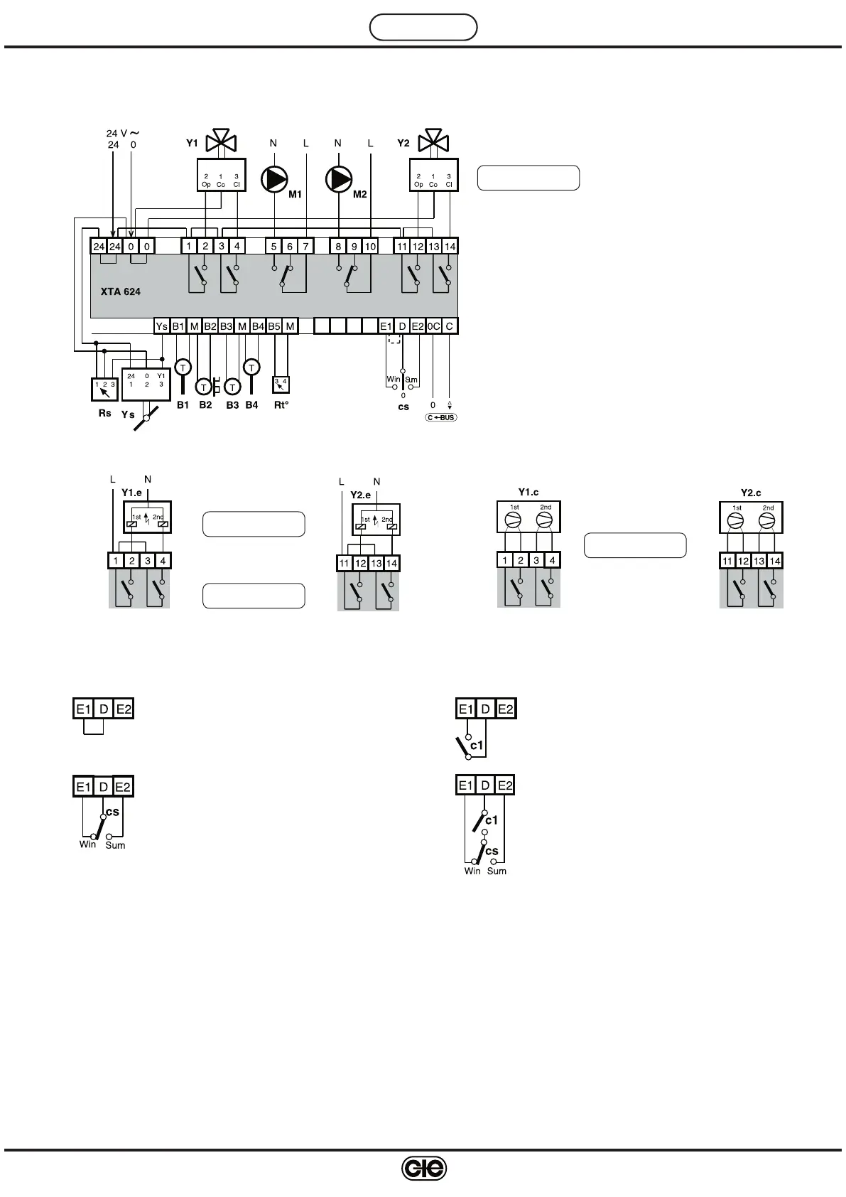
7. WIRING DIAGRAMS
B1 – Flow air temp. detector
B2 – Outside temp. detector
B3 – Room or extract air temp. detector
B4 – Preheating temp. detector
ss – Season switch (eliminate D-E1 link)
Win = Winter, Sum = Summer.
M 1-2 – Pump On-Off control
Y 1-2 – 3-wire modulating controls
Ys – Air dampers or recuperator 0...10V– control
Rt° – Temp. set-point adjuster
Rs – Minimum outside air positioner
C-Bus – Transmission data via Telemanagement; C-Bus
is enabled using the Plug-in type ACB 400 C1
7.4 Use of D-E1-E2 Outputs – Examples
ss – Control through manual or centralized season switch or through
XTU 614-type controller.
c1 – on-off contact through timeswitch or through manual control or
through fan relay
Y .. : M O D U L A T I N G
R un T i m e : x x x s
M2.3.5
7.1 3-Wire Modulating Valve Control
7.2 Electric Battery Control
Y .. : 2 S T A G E S
M2.3.5
2 equal loads
Y .. : 3 S T A G E S
M2.3.5
Y .. : 2 S T A G E S
M2.3.5
7.3 Direct Expansion Battery Control
2 unequal loads
Y1-2.e – Electric batteries
Y1-2.c – Direct expansion batteries (refrigerators)
8. WIRING
Proceed as follows :
• Separate base and cover
• Mount base on DIN rail and check that securing elements (5.
4) hold it firmly in place.
• Carry out wiring according to the diagram and in observance of the relevant regulations in force, and using cables of :
– 1.5 mm
2
for power and relay control outputs
– 1 mm
2
for sensors and remote control
– 1 mm
2
for C-Bus and C-Ring. For wire length limits please see technical data sheets T 021 and T 022
• Reposition the cover on the base / terminal block and fasten with the 4 screws supplied (5.
3).
• Check that voltage is correct and supplied by the dedicated auxiliary line, measuring it upstream of the protec-
tion (circuit breaker, fuse....).
• Power up the device.
You are advised not to insert more than two cables in a single terminal of the controller and if necessary to use external junction
boxes.
 Loading...