20
E 136 - XTA 624 C1 Eng. 22.11.10 AM REV. 02
We reserve the right to make changes without notice
COSTER
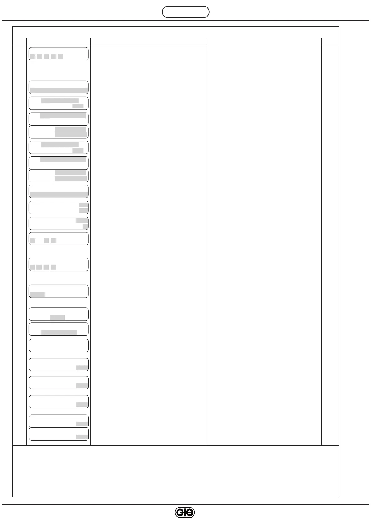
M3. EQUIPMENT CONFIGURATION
Ref. Display Description Notes Sect.
Configuration of connected detectors (outputs B-M)
– = detector not connected;
number = detector connected.
Default config.: no detectors connected
D e t e c t o r s L a y o u t
– – – – –
M3.1
1 : Flow temp. detector B1.
2 : Outside temp. detector B2
.
3 : Room or extract air temp. detector B3
.
4 : Preheating or dew point temp. detector B4
.
5 : Temperature set point adjuster Rt°
.
14.
Commutazione stagionale :
NO ; WINTER ; SUMMER; FR ss CONTROL ;
M3.
2
20.
S e a s o n S w i t c h i n g
N O
Output Y1 : MODULATING ; 2 STAGES ; 3 STAGES;
actuator stroke time in seconds
M3.
3
Stroke time: displayed only if MODULATING
18.
Y 1 : M O D U L A T I N G
R u n t i m e : 1 2 0 s
Output Y1 action.
Displayed if M2.
2 setting is NO
Y 1 : H E A T I N G
M3.4
Select action:
PREHEAT; HEATING; COOLING; OFF
18.
Y 1 - W i n : H E A T I N G
Y 1 - S u m : H E A T I N G
Output Y1 action in season periods.
Displayed if M2.
2 setting is NO
Output Y2 : MODULATING; 2 STAGES; 3 STAGES;
actuator stroke time in seconds
M3.
5
Stroke time: displayed only if MODULATING
18.
Y 2 : M O D U L A T I N G
R u n t i m e : 1 2 0 s
Output Y2 action.
Displayed if M2.
2 setting is NO
Y 2 : C O O L I N G
M3.6
Output Y2 action.
PREHEAT; HEATING; COOLING; OFF
18.
Y 2 - W i n : C O O L I N G
Y 2 - S u m : C O O L I N G
Output Y2 action in season periods.
Displayed if M2.
2 setting is NO
S e n d A l a r m s : N O
P a s s W T e l e m a n : N O
M3.8
Alarm transmission enabled.
Telemanagement password enabled
10.
4
Required only if connected through C-Bus
10.3
A d d r e s s : – – –
G r o u p : –
M3.9
Equipment Web address
Equipment group
Required only if connected through C-Bus
M3.10
23.1
Functional alarms enabled.
Default config.: Only alarm 8 enabled (cannot be
disabled)
1 : flow temperature difference B1
3 : room temperature differenceB3
4 : preheating temperature differenceB4
8 : internal clock alarm
A l a r m F u n c t i o n s
– – – 8
M3.11 A l a r m s D e t e c t o r
– – – –
23.2
Detector alarms enabled.
Default config.: all disabled
1 : flow temp. detector B1 malfunction
2 : outside temp. detector B2 malfunction.
3 : room temp. detector B3 malfunction
4 : preheating detector B4
.
M3.13 P a s s w o r d c h o i c e
- - - -
22.1
Select password to disable + and – keys:
1901 … 1999
To delete key press + and – simultaneously
M3.14
S i t e N a m e
- - - - - - - - - -
22.2
Set site name Use + and – to enter letters or numbers
Use
← and → to change positions
P b P r e h e a t i n g =
P b H e a t F l o w x 1 . 0
M3.17
Multiplier to obtain Pb of Preheating temp. from
heating flow Pb.
15.
2
Displayed if either output has been assigned the
function PREHEATING
T E C H N I C A L P A G E S
P R E S S + K E Y
P b F l o w =
P b R o o m x 5 . 0
M3.15
Multiplier to obtain Pbs of cooling temp. from
heating Pbs.
15.
2
Displayed if B1 and B3 are connected
P b C o o l i n g =
P c H e a t i n g x 0 . 5
M3.16
Multiplier to obtain Pbs of cooling temp. from
heating Pbs.
15.
2
Displayed if either output has been assigned the
function COOLING
Select Ys action:
DAMP.TEM.; RECUPER
Y s - C o n t r o l :
D A M P . T E M P .
M3.7
.
19.
P b D a m p e r s =
P b H e a t F l o w x 1 . 0
M3.18
Multiplier to obtain Pb of Air Damper Control from
room heating Pb.
15.
2
Displayed if B2 and B3 are connected, and if M2.7
setting is DAMP.TEMPERATURE
d T R e c u p e r a t o r =
P b H e a t F l o w x 1 . 0
Multiplier to obtain Pb of recuperator Control from
room heating Pb.
Displayed if
B2 and B3 are connected, and if M2.7
setting is RECUPERATOR
C B U S s p e e d
1 2 0 0 b p s
M3.12
The speed of the communication bus (C-Bus) can
be chosen from: 1200, 2400, 4800, 9600 bouds.
 Loading...