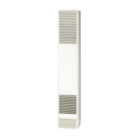
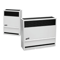
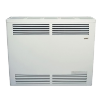
EasyManua.ls Logo

COZY CF353C-H User Manual

COZY CF353C-H
27 pages
To Next Page IconTo Next Page
Page #1 background imageLoading...
Page #1 background image
COUNTERFLOW
WALL FURNACE
INSTALLATION AND
OPERATING INSTRUCTIONS
P/N 78111 / REV. 03/2013
R
R
MODEL NUMBERS
24 VOLT SYSTEM NATURAL GAS CF353C-H CF503C-H CF653C-H
WITH LOW-BTU
PILOT L.P. GAS CF354C-H CF504C-H CF654C-H
24 VOLT SYSTEM NATURAL GAS CF357C-H CF557C-H
WITH INTERMITTENT
IGNITION (I.I.D.) L.P. GAS CF358C-H CF558C-H
This appliance is equipped
with a blocked flue switch
designed to protect against
improper venting of combus-
tion products.
THIS UNIT IS NOT TO BE
INSTALLED IN MOBILE
HOMES.
- Do not store or use gasoline or other flammable vapors and liquids in the
vicinity of this or any other appliance.
WHAT TO DO IF YOU SMELL GAS:
Do not try to light any appliance.
Do not touch any electrical switch; do not use any phone in your building.
Immediately call your gas supplier from a neighbor’s phone.
Follow the gas supplier’s instructions.
If you cannot reach your gas supplier, call the fire department.
- INSTALLATION AND SERVICE MUST BE PERFORMED
BY A QUALIFIED INSTALLER, SERVICE AGENCY OR
THE GAS SUPPLIER.
WARNING: If the information in this manual is not followed exactly, a fire or
explosion may result causing property damage, personal injury or loss of life.
WARNING: Operation of this furnace when not connected to a properly installed and maintained venting
system can result in Carbon Monoxide (C.O.) poisoning and possible death. For your safety, this furnace
and the venting system should be inspected at least annually by a qualified service technician.
The coating selected to provide longer life to the heat exchanger may smoke slightly upon initial firing. Please provide
adequate ventilation if this occurs.
This unit is for residential use only and is not approved for installation in mobile homes, greenhouses, or environments involving
dusty, wet, corrosive, or explosive conditions. Such conditions will invalidate the warranty and may create unsafe conditions.
INSTALLER: Leave this manual with the appliance.
CONSUMER: Retain this manual for future reference.
Installation, maintenance, service, troubleshooting and repairs must be performed by a qualified service agency. Mr./
Mrs. Homeowner, DO NOT attempt any of these procedures yourself as this could expose you to property damage,
personal injury or loss of life and will invalidate all warranties.

Questions and Answers:

COZY CF353C-H Specifications

General IconGeneral
BrandCOZY
ModelCF353C-H
CategoryFurnace
LanguageEnglish

Summary

MODEL NUMBER IDENTIFICATION

INTRODUCTION AND SPECIFICATIONS

PRODUCT OVERVIEW

Provides essential safety and operational information for the gas-fired wall furnace.

FURNACE SPECIFICATIONS

Details technical specifications, including BTU/HR, vent size, gas type, and dimensions for various models.

SAFETY RULES AND VENTING

GENERAL SAFETY GUIDELINES

Outlines critical safety precautions for installation, operation, and maintenance to prevent injury or property damage.

VENTING REQUIREMENTS

Specifies mandatory venting system requirements, including pipe type, offsets, and termination points for safe operation.

VENTING DETAILS AND SWITCH FUNCTIONS

VENTING DIAGRAMS AND RULES

Illustrates venting installation best practices and rules regarding offsets and horizontal runs.

BLOCKED FLUE SWITCH FUNCTION

Explains the purpose and operation of the blocked flue switch, including reset procedures and safety warnings.

COMBUSTION AND VENTILATION AIR

AIR SUPPLY REQUIREMENTS

Details minimum air volume requirements for combustion and ventilation, specifying openings for confined and unconfined spaces.

INSTALLATION PREPARATION

LOCATION AND CLEARANCES

Specifies acceptable furnace locations and required clearances from combustible materials for safe installation.

ELECTRICAL ROUGH-IN

Provides instructions for making necessary electrical connections, including wiring and junction box requirements.

GAS ROUGH-IN

GAS LINE CONNECTIONS

Details requirements for gas line sizing, joint preparation, leak testing, and drip leg installation according to codes.

INSTALLATION PROCEDURES

RECESSED INSTALLATION

Step-by-step guide for installing the furnace when recessed into a wall, including vent and electrical connections.

FLUSH TO WALL INSTALLATION

Step-by-step guide for installing the furnace flush to the wall, covering vent collar, ceiling plate, and electrical connections.

CONTROLS AND PILOT ADJUSTMENT

GAS CONTROL COMPONENTS

Identifies key control components like the VR8200H and VR8204H series valves and their functions.

PILOT FLAME ADJUSTMENT

Provides instructions on how to adjust the pilot flame to the correct size and position for reliable ignition.

STANDING PILOT LIGHTING

SAFETY BEFORE LIGHTING

Critical safety warnings and procedures to follow before attempting to light the pilot light, including gas leak detection.

LIGHTING INSTRUCTIONS

Detailed step-by-step instructions for safely lighting the pilot and operating the furnace.

TURNING OFF GAS

Procedures for safely shutting off the gas supply to the appliance for service or other purposes.

I.I.D. PILOT LIGHTING

SAFETY BEFORE OPERATION

Essential safety precautions before operating the I.I.D. pilot system, emphasizing automatic ignition and gas leak checks.

LIGHTING INSTRUCTIONS

Step-by-step guide for operating the furnace with an intermittent ignition device, including safety checks.

BURNER FLAME AND OPERATION

PROPER BURNER FLAME

Describes the visual characteristics of a proper burner flame and notes on derating for altitude.

FURNACE OPERATION MODES

Explains the slow opening gas control and automatic two-speed fan operation for efficient heating.

WIRING AND MAINTENANCE

TERMINAL BLOCK WIRING DIAGRAMS

Illustrates wiring connections for different model series, including transformer, motor, and limit switches.

AUXILIARY LIMIT SWITCH

Details the function of the auxiliary limit switch and its manual reset procedure for safety.

MAINTENANCE INSTRUCTIONS

Provides guidelines for regular cleaning, lubrication, and inspection by qualified technicians to ensure safe and efficient operation.

WIRING DIAGRAMS

STANDING PILOT SCHEMATICS

Pictorial and ladder schematics for standing pilot models, showing electrical pathways and component connections.

I.I.D. PILOT SCHEMATICS

Pictorial and ladder schematics for intermittent ignition models, detailing ignition module and control connections.

ROUGH-INS AND ACCESSORY KITS

ROUGH-IN DIMENSIONS

Illustrates required rough-in dimensions and plasterground placement for rear and side discharge configurations.

ACCESSORY KITS OVERVIEW

Introduces available accessory kits for register installation, including flush and recess options for rear and side discharge.

OPTIONAL ACCESSORY KITS CONTINUED

SIDE DISCHARGE KITS

Details installation for side discharge kits, including standard and extension boot configurations.

PLUG EXTENSION KIT

Instructions for installing the 14PEK-A plug extension kit for non-recessed installations, covering wiring and raceway setup.

TROUBLESHOOTING GUIDE

MAIN BURNER ISSUES

Lists common main burner symptoms, their possible causes, and corrective actions for qualified technicians.

PILOT AND GAS VALVE ISSUES

Addresses troubleshooting for pilot and gas valve problems, including common causes and solutions for service personnel.

INTERMITTENT IGNITION DIAGNOSTICS

Provides a guide to troubleshooting intermittent ignition systems using LED flash codes and system actions.

REPLACEMENT PARTS IDENTIFICATION

STANDING PILOT ASSEMBLY

Diagram showing the exploded view of the standing pilot furnace, labeling key components for identification.

ORDERING PARTS

Instructions on how to order parts, requiring model number, serial number, and gas type, along with a parts list.

REPLACEMENT PARTS IDENTIFICATION (I.I.D.)

I.I.D. PILOT ASSEMBLY

Diagram showing the exploded view of the I.I.D. pilot furnace, labeling key components for identification.

ORDERING PARTS (I.I.D.)

Instructions on ordering parts for I.I.D. models, requiring specific details and providing a comprehensive parts list.

ACCESSORY KITS AND WIRING

ACCESSORY KITS

Illustrates various kits for vent enclosure, trim, and register installation, including diagrams for proper fitting.

REPLACEMENT WIRING HARNESSES

Lists replacement wiring harnesses for standing pilot and I.I.D. models, specifying connections and lengths.

BLOCKED FLUE SWITCH TROUBLESHOOTING

CAUSES AND CORRECTIVE ACTIONS

Provides a detailed list of possible causes and corrective actions for blocked flue switch problems, intended for qualified technicians.

LIMITED WARRANTY

WARRANTY COVERAGE AND CLAIMS

Outlines the terms of the limited warranty, including coverage periods, installer responsibilities, and claim procedures.

Related product manuals