Do you have a question about the Crafco SUPER SHOT 125 and is the answer not in the manual?
Guidelines for protective clothing, eye protection, and handling hot materials.
Safe practices for temperature limits, fluid levels, and equipment operation.
Details on warranty coverage, periods, and conditions for Crafco equipment.
Step-by-step instructions for submitting a warranty claim and required information.
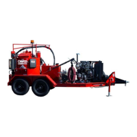
Key technical specifications of the Super Shot 125 Diesel Melter.
Overview of operating procedures and operator responsibility.
Essential checks for fuel, oil, and fluid levels before starting the machine.
Step-by-step guide for starting the burner and heating systems.
Instructions for applying sealant, pump control, and safety during dispensing.
Procedures for loading sealant, shutting down, and storing the equipment.
Guidance on ordering parts and essential care for the heated electric hose.
Instructions for transporting the heated hose to prevent damage.
Maintenance tasks for key systems like engine, hydraulics, and burner.
Procedures for checking fluids, bearings, and calibrating temperature controls.
Maintenance chart based on hours and general service guidelines.
List of recommended fluids and lubricants for the melter, including oil specifications.
Step-by-step guide for removing and reinstalling the material pump.
Diagram illustrating the pump assembly and its mounting on the tank bottom.
Troubleshooting steps to identify why the heated hose is not functioning correctly.
Schematic of the electrical circuit for the heated hose system.
Steps to diagnose when the pump runs but no material is dispensed.
Hose circuit schematic relevant to material dispensing operations.
Troubleshooting for pump operation without material output.
Steps to address issues causing a slow material dispensing rate.
Chart correlating RTD sensor resistance (ohms) to specific temperature values.
Key settings and adjustment parameters for the diesel burner operation.
Schematic diagram of the electrical circuit for the diesel burner assembly.
Diagnosing problems with burner ignition, shutdown, and relighting.
Troubleshooting excessive smoke and other burner performance problems.
Diagram illustrating the flow of hydraulic fluid through the system.
Table listing common hydraulic problems, their causes, and remedies.
Illustrations of the SS 125 Melter assembly with numbered parts.
List of Crafco SS 125 Melter parts, items 1 through 23.
List of Crafco SS 125 Melter parts, items 24 through 49.
List of Crafco SS 125 Melter parts, items 50 through 60.
Illustration of the melter tank and its numbered components.
Detailed list of parts for the melter tank assembly.
Diagram showing the wiring and components within the melter's control box.
Detailed list of parts for the melter's control box assembly.
Diagram showing the engine assembly, generator, and related parts.
Detailed list of parts for the engine assembly, including filters and drive components.
Diagram and parts list for the hydraulic control valve assembly.
Diagram and parts list for the pump and agitator motor assembly.
Illustration of the diesel burner with numbered components.
Detailed list of parts for the diesel burner, including ignition and fuel components.
Diagram showing the overall hydraulic system flow and major components.
Detailed breakdown of hydraulic hoses, adapters, and fittings used in the system.
Wiring diagram for the junction box, showing connections to various melter components.
List of part numbers and descriptions for electrical cable assemblies.
| Brand | Crafco |
|---|---|
| Model | SUPER SHOT 125 |
| Category | Melting Machines |
| Language | English |