III. INSTALLATION OF WALL CONTROL
[PLEASE NOTE: Wall and/or handheld remote control must be used for
fan to operate. If you do not wish to use the wall control, please proceed
to Part IV for handheld remote control assembly instructions.]
A. Remove existing wall switch.
B. Wire one of the wall controls with wire connectors provided as
shown in Fig. 5.
WARNING: Do not mount wall control near heat-producing
equipment.
C. Wrap each wire connector separately with electrical tape as an
extra safety measure. Gently push wires and taped wire
connectors into outlet box.
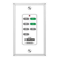
D. Use a small screwdriver or ballpoint pen to set code switches on
the wall control by sliding them firmly to your choice of on or off /
left or right position. (Do not use factory setting/position.) (See
Fig. 5)
E. The dimmer switch (labeled D and O) has been pre-set to the
"ON" position (D). If you do not wish to have dimming capability
or are using bulbs that are not capable of being dimmed, please
move the switch to the "OFF" position (O). (See Fig. 5)
NOTE: Most LED and compact fluorescent bulbs are not
compatible for use with dimmer controls.
F. Install one 12-volt battery (included) in wall control. (See Fig. 5)
IMPORTANT: Wall control will not function unless battery is installed.
G. Select a faceplate (almond or white) and press firmly onto front of wall
control. Attach wall control to outlet box and secure with screws from
original wall switch. Attach wall plate (included) to wall control using 2
screws provided with the wall control. (See Fig. 5)
INSTALLATION AND OPERATING INSTRUCTIONS
I. SAFETY PRECAUTIONS
A. READ ALL INSTRUCTIONS AND SAFETY INFORMATION CAREFULLY BEFORE INSTALLING YOUR CONVERSION KIT AND SAVE THESE INSTRUCTIONS.
B. DANGER: HIGH VOLTAGE! Household electrical power can cause serious injury or death. Disconnect source of electrical power to the ceiling fan by removing fuse or switching off
circuit breaker. Make sure all electrical connections comply with local codes and ordinances, the National Electrical Code and ANSI/NFPA 70-1999. If you are unfamiliar with electrical
wiring, please use a qualified and licensed electrician.
C. CAUTION: TO REDUCE THE RISK OF FIRE OR ELECTRIC SHOCK, DO NOT USE THE FAN WITH ANY SOLID STATE SPEED CONTROL DEVICE OR CONTROL FAN SPEED
WITH A FULL RANGE DIMMER SWITCH.
D. Do not use this remote control with solid state ceiling fans.
Electrical source and fan must be 115/120 volts, 60 Hz. Maximum fan motor amps: 1; Maximum light watts: 360, incandescent only
II. INSTALLATION OF RECEIVER
A. Disconnect source of electrical power to the ceiling fan by removing fuse
or switching off circuit breaker.
WARNING: Failure to disconnect power supply prior to installation may
result in serious injury.
B. Loosen and/or remove screws from existing switch housing and lower
switch housing--save screws for later use. (See Fig. 1 for example.)
C. Disconnect existing wiring between motor housing and switch housing
and then remove existing switch housing. (See Fig. 1 for example.)
D. Remove screws from metal plate at top of replacement switch housing
and remove metal plate. (See Fig. 2)
E. Place receiver module inside replacement switch housing. Re-attach
metal plate with screws that were removed. [IMPORTANT: Metal plate
must be turned with the raised edge facing up.] (See Fig. 3)
F. Connect male plug from motor housing to female plug in receiver
module located inside replacement switch housing. (See Fig. 4 for
example.)
G. Make sure all wiring is tucked inside switch housing. Attach replacement
switch housing to motor housing with screws that were previously
loosened/removed. (See Fig. 4 for example.) Tighten all screws securely.
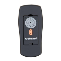
MODEL: ICS2 CONVERSION KIT
GENERAL INFORMATION
This remote control is designed to separately control your ceiling fan speed and, if applicable, light brightness.
There are eight buttons to control the fan and two buttons to control the lights.
p. 1
motor
housing
Fig. 1
switch housing
(existing)
receiver
module
metal
plate
metal
plate
raised edge
motor
housing
replacement
switch housing
Fig. 2
Fig. 3
Fig. 4
Fig. 5
Modifications not approved by the party responsible for compliance could
void the user's authority to operate the equipment.
*NOTE: This equipment has been tested and found to comply with the limits for a Class B digital device,
pursuant to Part 15 of the FCC Rules. These limits are designed to provide reasonable protection against
harmful interference in a residential installation. This equipment generates, uses and can radiate radio
frequency energy and, if not installed and used in accordance with the instructions, may cause harmful
interference to radio communications. However, there is no guarantee that interference will not occur
in a particular installation. If this equipment does cause harmful interference to radio or television
reception, which can be determined by turning the equipment off and on, the user is encouraged to try
to correct the interference by one or more of the following measures:
[representative drawing]
[representative drawing]
replacement
switch housing
replacement
switch housing
replacement
switch housing
* Reorient or relocate the receiving antenna.
* Increase the separation between the equipment and receiver.
* Connect the equipment into an outlet on a circuit different from that to which the
receiver is connected.
Consult the dealer or an experienced radio/TV technician for help.
1234
D
ON
O
L
DO
LEARN
M
H
1hr
3hr
6hr
12V
black (OUT to fan)
green
black
(AC IN from
breaker box)
black
(TO POWER supply)
black
green/
bare
ground
outlet box
wall control
face-
plate
12V battery
wall plate
dimmer
switch
code
switches