EasyManua.ls Logo

Craftmade TCS Plus - User Manual

Craftmade TCS Plus
20 pages
Print Icon
To Next Page IconTo Next Page
Loading...
P. O. Box 1037
650 S. Royal Lane, Suite 100
Coppell, TX 75019 EE.UU.
(800) 486- 4892
8:00 a 5:00 CST (Hora local central)
Número de fax sin cargo: (877) 304-1728
Correo electrónico: customerservice@craftmade.com
www. craftmade.com
®
MEJOR DISEÑO
®
UNE CONCEPTION EXCEPTIONNELLE
P. O. Box 1037
650 S. Royal Lane, Suite 100
Coppell, TX 75019 EE.UU.
de 8 heures à 17 heures (Heure standard du centre)
Numéro de télécopieur gratuit : (877) 304-1728
Email: customerservice@craftmade.com
www. craftmade.com
P.O. Box 1037
650 S. Royal Lane, Suite 100
Coppell, TX 75019
(800) 486-4892
8:00 to 5:00 CST (Central Standard Time)
Toll Free Fax: (877) 304-1728
email: customerservice@craftmade.com
www.craftmade.com
®
BETTER BY DESIGN
TCS-Plus
®
Installation Instructions
TCS-Plus® Remote Control System
®
BETTER BY DESIGN
OFF
12V BAT.
ON
HI
MED
LO W
OFF
L-1
L-2
REV
Question and Answer IconNeed help?

Do you have a question about the Craftmade TCS Plus and is the answer not in the manual?

Craftmade TCS Plus Specifications

General IconGeneral
BrandCraftmade
ModelTCS Plus
CategoryRemote Control
LanguageEnglish

Summary

Craftmade TCS-Plus Remote Control System Installation

Safety Precautions

Remote Control Operation

Fan Controls

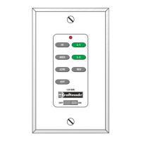
Includes ON/OFF, speed selection (High, Medium, Low), and reverse function for fan operation.

Light Controls

Controls on/off and intensity for optional bottom and side body lighting (L-1, L-2).

Setting Frequency Switches

Installation Steps

Step 1: Disconnect Power

Turn off power at circuit breakers and wall switch before proceeding with wiring.

Step 2: Connect Wiring

Remove existing housing, unplug modular wires, and connect new plugs firmly.

Step 3: Mount Switch Housing

Align and secure the switch housing to the mounting plate with screws.

Step 4: Wiring Instructions

Connect wires according to the diagram, ensuring correct polarity and secure connections.

Wiring Applications

Diagram 1: Single Pole Wiring

Wiring configuration for a fixture controlled by two switches, powered through a switch box.

Diagram 2: Three-Way Wiring

Wiring for a fixture between two three-way switches, powered through a switch.

Diagram 3: Three-Way Wiring with Power at Light Box

Wiring for a fixture between three-way switches with power source at the light box.

Diagram 4: Three-Way Wiring from Ceiling Box

Wiring for a fixture controlled by two switches, powered through the ceiling box.

Related product manuals