3
Step 3
1. To install the Switch Housing Assembly (#9), locate both modular
wiring plugs (A) and (B). One extends from the mounting plate (E) on
bottom of fan body and one extends from the Switch Housing (#9).
Align the two plugs so the latch on the side of the plugs will engage when
pushed together. Push the two plugs firmly together until latched.
2. Loosen 2 of the 3 screws (F) on mounting plate. Completely remove
one of the screws. Raise switch housing (#9) and align the mounting
slots (D) in the switch housing with the mounting screws (F) on the
mounting plate on bottom of fan body. Rotate the switch housing to the
right until the two screws are completely seated into mounting slots.
Replace screw that was removed. Tighten the three mounting screws
securely.
IMPORTANT: Be sure that no wires are caught in mounting slots or pinched between
switch housing and mounting plate.
Modular Wiring Plug (A)
Modular Wiring Plug (B)
Switch Housing (9)
Screws (F)
Mounting Slots (D)
Placa de montaje (E)
4
Step 4
Wiring Instructions
NOTE: Use instructions packed with celing fan to wire ceiling fan.
WARNING: To avoid overheating and possible damage to his device and
other equipment, do not install to control a receptacle, fluorescent lighting,
transformer, or motor-operated appliance other than the fans for which this
control is intended. Use this device only with copper or copper clad wire.
With aluminum wire use only devices marked CO/ALR.
1. Remove insulation to expose 3/4" bare copper wire at end of circuit
conductors. Keep wire ends straight.
2. Connect wires per wiring diagram as follows: black leads (one each) to
black (hot) line, green ground wire to copper outlet wire. Hold bare
ends together. Push wires firmly into wire connector. Screw connector
on clockwise until no bare copper shows. Secure connector with electrical
tape.
CAUTION: Never attach white neutral wire to TCS+ Control
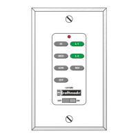
3. Make sure battery is properly installed in switch. The switch should
already have this preinstalled, but double check before installing the
mounting plate (see diagram). Note: The battery replacement code is
23A 12Volt.
4. Mount device with long mounting screws (provided). Install wallplate
and tighten cover screws.
5. Restore power at circuit breaker or fuse. Installation is complete.
Neutral
(White Wire)
Hot Line
(Black Wire)
SINGLE POLE
Neutral
(White Wire)
Load
(Black Wire)
23A 12Volt
Battery
HI
MED
LOW
OFF
L-1
L-2
REV
OFF
ON
12V. BATT.
SUPER
23A 12V
1234
ON
Ground Wire
(Copper Wire)
Ground Wire
(Green Wire)