Step 2
Remove existing switch housing cover by unscrewing the side screws (F)
on unit. This will allow switch housing unit to drop. Unplug the modular
wiring (A) and (B) and remove the existing switch housing unit.
2
Using the TCS-PLUS
®
module, locate both modular wiring plugs (A)
& (B), one extending from the mounting plate on the bottom of the
motor housing and one on the switch housing. Align the two plugs so
that when pushed together the latch on the sides of the plugs will engage.
Push the two plugs firmly together until latched. (Make sure that all wires
are firmly seated into plastic connectors.
Modular Wiring Plug (A)
Modular Wiring Plug (B)
Switch Housing (9)
Screws (F)
Mounting Slots (D)
Mounting Plate (E)
Preparation
Step 1
Turn off circuit breakers and wall switch to the fan
supply line leads.
1
Warning: Failure to disconnect power supply prior to
installation may result in serious injury or death.
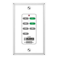
Setting Frequency Switches
The wall control unit is operated by a set of frequency switches and are
preset at the factory. The switches are located on the side of the wall unit
and in the lower part of the fan on the receiving module. The switches
can be set in any position as long as both the wall unit and receiving
module switches are set the same. All (RF) modules & Transmitters come
from the factory with the dip switches set in the (ON) position.
1234
ON
HI
MED
LOW
OFF
L-1
L-2
REV
OFF
ON
12V. BATT.
SUPER
23A 12V
1234
ON
1234
ON