i..... ii, r,..,.,,,, I Ill' I''
ASSEMBLY INSTRUCTIONS
-- ................ f I I '111 _ ,1_..11 '1 J iJ_l H jlj
IMPORTANT: This unit is shipped WITHOUT
GASOLINE or OIL. After assembly, be certain to ser-
vice engine with gasoline and oil before operating
your mower.
NOTE: Reference to right or left hand side of the
mower is observed from the operating position.
Tools Required for Assembly
(1) Pair of Pliers
(2) 7/16" Wrenches or Adjustable Wrenches
(1) Flat Bladed Screwdriver
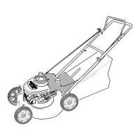
UNPACKING
• Remove the lawn mower from the carton by open-
ing the top flaps and lifting the unit out. Be careful
of the staples. Make certain all parts and literature
have been removed from the carton before the car-
ton is discarded
• Disconnect the spark plug wire from the spark plug
and ground against the engine,
e Stretch out control cable and place on the floor,. Be
careful not to bend or kink the cable at any time dur-
ing assembly
@ Lay out the contents of the hardware pack accord-
ing to the illustration on page 5 for identification
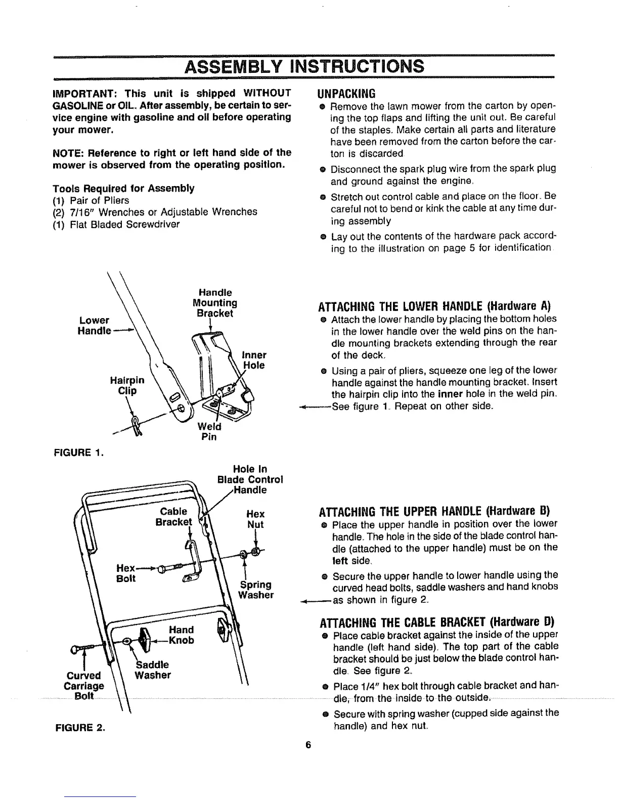
k_\\ Handle
\ \ Mounting
Lower \\ \ Bracket
).\.
FIGURE 1.
Hole In
Blade Control
lie
Cable Hex
Bracket Nut
Bolt
Spring
Washer
Hand
Curved
Carriage
..........................Bolt .................
Washer
FIGURE 2.
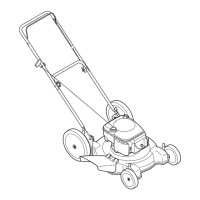
ATTACHING THE LOWER HANDLE (Hardware A)
® Attach the lower' handle by placing the bottom holes
in the lower handle over the weld pins on the han-
dle mounting brackets extending through the rear
of the deck.
e Using a pair' of pliers, squeeze one leg of the lower'
handle against the handle mounting bracket, Insert
the hairpin clip into the inner hole in the weld pin_
-.-------See figure 1_Repeat on other side.
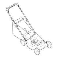
ATTACHINGTHE UPPERHANDLE(HardwareB)
• Place the upper handle in position over the lower
handle. The hole in the side of the blade control han-
dle (attached to the upper handle) must be on the
left side.
® Secure the upper handle to lower handle using the
curved head bolts, saddle washers and hand knobs
-._------as shown in figure 2.
ATTACHINGTHE CABLEBRACKET(Hardware D)
• Place cable bracket against the inside of the upper
handle (left hand side), The top part of the cable
bracket should be just below the blade control han-
dle See figure 2o
e Place 114" hex bolt through cable bracket and han-
dte_ from the inside to the outside_ ...................................................................................................................................................
e Secure with spring washer (cupped side against the
handle) and hex nut,,
 Loading...