EasyManua.ls Logo

Craftsman 320.28084 User Manual

Craftsman 320.28084
68 pages
To Next Page IconTo Next Page
Page #1 background imageLoading...
Page #1 background image
Product Manual
PRQFESS|ONAL
12.5 Amp, Variable Speed, 2-114
Peak HP Router Combo
with Fixed Base, Plunge Base,
and D-Handle Base
Model No. 320. 28084
CAUTION! Read, understand and
follow all Safety Rules and Operating
instructions in this Manual before
using this product.
= Warranty
= Safety
= Assembly
= Description
= Operation
= Maintenance
= Troubleshooting
Sears, Roebuck and Co., Hoffman Estates, IL 60179
www.craftsman.com

Table of Contents

Question and Answer IconNeed help?

Do you have a question about the Craftsman 320.28084 and is the answer not in the manual?

Craftsman 320.28084 Specifications

General IconGeneral
BrandCraftsman
Model320.28084
CategoryPower Tool
LanguageEnglish

Summary

Safety Symbols

Symbol Meanings

Explains the meaning and significance of different safety alert symbols used in the manual.

Damage Prevention and Information Messages

Provides guidance on interpreting "NOTE" messages for preventing equipment or property damage.

Safety Instructions

Work Area Safety

Covers safety guidelines for maintaining a clean, well-lit, and hazard-free work area.

Personal Safety

Outlines essential personal safety practices for operating the router, including alertness and proper attire.

Electrical Safety

Extension Cords

Provides guidelines on selecting and using appropriate extension cords for the router.

Safety Symbols for Your Tool

Service Safety

Safety Rules for Routers

Additional Rules for Safe Operation

Unpacking

Parts List (Fig. 1)

Description

Know Your Router Combo (Fig. 2)

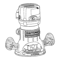
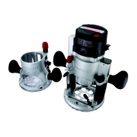
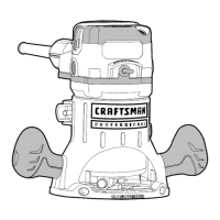
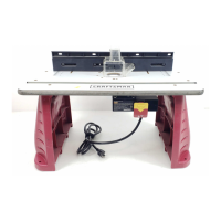
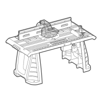
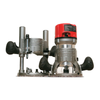
Details the various components and features of the router combo, with illustrations.

Product Specifications

Assembly

Operation

Detachable Power Cord (Figs. 3, 3a and 3b)

Details the procedure for attaching and detaching the router's power cord for ease of use.

Operation

Toggle "On/Off" Switch (Fig. 4)

Explains how to turn the router motor on and off using the toggle switch.

Trigger Switch and Lock-On Button for D-Handle Base Router (Fig. 5)

Details the operation of the trigger switch and the lock-on button for the D-handle base.

Operation

Live-Tool Indicator Light (Figs. 6 and 6a)

Describes the live-tool indicator light that shows when the router is powered.

Selecting the Cutting Bit

Installing and Removing the Cutting Bit (Figs. 7, 8, 8a)

Installing the Cutting Bit

Provides a step-by-step guide for securely installing a cutting bit into the router's collet.

Installing and Removing the Cutting Bit

Removing the Cutting Bit

Explains the process for safely removing a cutting bit from the router's collet.

Collet/Nut Care

Offers guidance on inspecting, cleaning, and maintaining the collet and nut for optimal performance.

Installing and Removing the Router Motor

To Install Router Motor in Fixed Base (Fig. 9)

Guides the user through the process of mounting the router motor into the fixed base.

Installing and Removing the Router Motor

To Install Router Motor in Plunge Base (Fig. 10)

Details the steps for securing the router motor into the plunge base.

To Install Router Motor in D-Handle Base (Fig. 11)

Provides instructions for mounting the router motor into the D-handle base.

To Remove Router Motor From Fixed Base (see Fig. 9)

Outlines the procedure for safely removing the router motor from the fixed base.

Installing and Removing the Router Motor

To Remove Router Motor From Plunge Base (see Fig. 10)

Details the steps for detaching the router motor from the plunge base.

To Remove Router Motor From D-handle Base (see Fig. 11)

Guides the user through removing the router motor from the D-handle base.

Three Mounting Positions For Auxiliary Handle Of D-Handle Base (Fig. 12)

Adjusting Depth of Cut

Depth Adjustment with Fixed Base (Figs. 13 and 14)

Coarse Adjustment

Details how to use the coarse adjustment knob for initial depth setting.

Fine Adjustments

Describes the process of fine-tuning the cutting depth using the adjustment dial and indicator ring.

Depth Adjustment with the Plunge Base

Plunge Action (Fig. 15)

Depth-Stop Rod and Depth-Stop Turret (Figs. 16 and 17)

Making Deep Cuts with the Depth-Stop Turret (Fig. 17)

Provides instructions for making multiple passes to achieve deep cuts using the depth-stop turret.

Micro Adjustments with the Depth-Stop Rod and Depth-Stop Turret

Depth Adjustment with D-Handle Base (Figs. 18 and 19)

Coarse Adjustment

Describes the coarse depth adjustment mechanism for the D-handle base.

Fine Adjustments

Details the fine adjustment process for the D-handle base using the indicator ring.

Depth Adjustment with D-Handle Base

To Adjust Depth (Figs. 18 and 19)

Provides step-by-step instructions for setting the cutting depth on the D-handle base.

Deep Cuts (Fig. 20)

LED Worklights (Fig. 21)

Heavy-Duty Edge Guide (Figs. 22, 22a and 22b)

Electronic Variable Speed Control (Fig. 23)

Placing the Router onto the Workpiece and Starting the Cut

Edge Routing (Figs. 24, 24a and 24b)

Internal Routing with Fixed Base (Figs. 25, 25a, 25b)

Internal Routing with Plunge Base (Figs. 27 and 27a)

Internal Routing with D-Handle Base (Figs. 28, 28a, 28b and 29)

Freehand Routing (Fig. 30)

Edging with a Pilot Bit (Figs. 31 and 31a)

Feeding the Router (Fig. 32)

Direction of Feed - External Cuts (Fig. 32)

Illustrates and explains the correct direction of feed for external routing operations to ensure control.

Kickback

Defines kickback, its causes, and provides strategies to prevent it during routing.

Direction of Feed - Internal Cuts (Figs. 33 and 33a)

Rate of Feed (Figs. 34 and 34a)

Feeding Too Rapidly (Fig. 34)

Describes the effects of feeding the router too quickly, leading to rough cuts and overheating.

Feeding Too Slowly (Fig. 34a)

Details the issues caused by feeding the router too slowly, such as scraping and heat buildup.

Chip Shields (Figs. 35, 35a and 35b)

Dust Extraction Hoods (Figs. 36, 36a and 36b)

Dust Extraction Hood for Fixed Base (Fig. 36)

Provides instructions for attaching the dust extraction hood to the fixed base of the router.

Dust Extraction Hoods

Dust Extraction Hood for Plunge Base (Fig. 36a)

Details the process for attaching the dust extraction hood to the plunge base.

Dust Extraction Hood for D-Handle Base (Fig. 36b)

Guides the user on attaching the dust extraction hood to the D-handle base.

To Adjust Depth with Depth-Adjustment Wrench (Figs. 37, 37a and 37b)

Maintenance

General

Provides general guidelines for tool maintenance, service, and precautions related to specific materials.

Routine Maintenance

Outlines regular maintenance procedures to ensure the tool's smooth functioning and longevity.

Replacement of Carbon Brushes (Fig. 38)

Lubrication

Accessories

Parts List

Router Motor Unit

Details the individual components of the router motor unit with corresponding part numbers.

Parts List

Fixed Base

Itemizes the components specific to the router's fixed base.

Parts List

Plunge Base

Details the parts included in the plunge base assembly.

Parts List

D-Handle Base

Itemizes the components that make up the D-handle base.

Parts List

Accessories

Details the various accessory parts available for the router.

Related product manuals