Do you have a question about the Craftsman 81998 and is the answer not in the manual?
Customer assistance contact information and operating hours for warranty and support inquiries.
Crucial safety warning emphasizing extreme caution due to potential for injury or death from improper use.
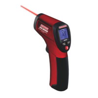
Emphasizes the need for extreme caution when the laser pointer function is active.
Prohibits directing the laser beam at eyes or allowing it to reflect into eyes.
Advises against using the laser in environments with explosive gases or potential explosion hazards.
Mandates turning off power and disconnecting leads before accessing internal components like fuses or batteries.
Prohibits operating the meter without the back cover properly secured.
A critical caution regarding laser radiation, warning users not to stare directly into the beam.
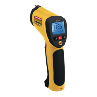
Identifies the laser pointer component of the thermometer.
Identifies the Infrared sensor responsible for non-contact temperature measurement.
Describes the trigger used to activate the thermometer for measurements.
Locates the compartment for the battery and internal switches.
Refers to the Liquid Crystal Display showing measurement data and status.
Identifies the buttons used for operating various functions of the thermometer.
Identifies the input for the Type-K thermocouple probe.
Describes the switch for selecting temperature units (°C or °F).
Identifies the switch to enable or disable the test lock feature.
Identifies the switch for controlling the audible/visual alarm functions.
Provides a note about the location of the switches within the battery compartment.
Specifies the technical details for the IR non-contact thermometer function.
Specifies the technical details for the Type K contact thermometer function.
Details the specifications for the included Type K bead wire probe.
Describes the display characteristics, including backlight and indicators.
Specifies the approximate response time of the thermometer.
Explains how the meter indicates measurements exceeding its range.
Defines the recommended temperature range for operating the device.
Specifies the maximum recommended operating humidity level.
Defines the recommended temperature range for storing the device.
Specifies the maximum recommended storage humidity level.
Indicates the type of battery required for the thermometer's operation.
Describes the automatic power-off feature and its duration.
Provides the weight of the thermometer.
Lists the physical dimensions of the thermometer.
Instructs to replace the 9V battery when the low battery symbol is shown on the display.
Details the location of the battery compartment relative to the meter's trigger.
Explains the procedure to open the battery compartment by pulling down the panel.
Guides the user on replacing the 9V battery and closing the compartment.
Provides a troubleshooting tip to check battery installation and condition if the meter malfunctions.
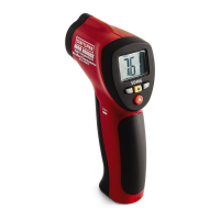
Step-by-step guide for performing temperature measurements using the IR function.
Instructions on how to hold and aim the meter for IR temperature measurement.
Explains how to activate the meter and start testing by pulling the trigger.
Describes what information is displayed on the LCD during a measurement.
Explains the HOLD function and automatic shut-off after releasing the trigger.
Notes that the LOCK mode overrides the automatic shut-off feature.
Reminds users to select temperature units via the switch in the battery compartment.
Instructions for turning on the backlight by using the trigger and button.
Explains how to activate the laser pointer by pressing the button again.
Describes how to turn off the backlight using the laser button.
Explains how to turn off the laser pointer by pressing the button again.
Informs that backlight and laser settings are maintained across power cycles.
Instructions for connecting the Type-K thermocouple probe to the instrument.
Explains that pulling the trigger powers on the instrument for Type-K measurements.
Details methods to keep the instrument powered on during testing, including trigger hold or lock switch.
Guides on using the MODE button to select the Type-K temperature display.
Explains how to read the Type-K temperature measurement on the LCD.
Instructions on positioning the thermocouple for contact temperature measurement.
Indicates where the measured value from the thermocouple is displayed.
Provides the temperature rating for the included Type-K thermocouple.
Informs about purchasing higher-temperature thermocouples from the Craftsman website.
Explains how to select temperature units using a switch in the battery compartment.
Describes the Test LOCK feature, which keeps the meter in scan mode.
Highlights the benefits of the Test LOCK feature for continuous monitoring.
Instructs on activating the LOCK feature by setting a specific switch in the battery compartment.
Explains how to adjust and use the Emissivity Value (EMS) setting.
Describes the MAX mode for displaying the highest reading in a session.
Describes the MIN mode for displaying the lowest reading in a session.
Explains the DIF mode, which shows the difference between MAX and MIN readings.
Describes the AVG mode for displaying the average of all readings in a session.
Explains the HAL setting for programming the high temperature alarm threshold.
Explains the LAL setting for programming the low temperature alarm threshold.
Describes the Tk function for displaying Type-K thermocouple readings.
Explains how Type-K probe readings are displayed on the LCD.
Indicates that '-----' on the display means the Type-K sensor is improperly inserted.
States the temperature rating for the included Type-K thermocouple.
Informs about purchasing higher-temperature thermocouples from the Craftsman website.
States the thermometer's capability for automatic emissivity calibration.
Specifies the minimum surface temperature requirement for automatic emissivity adjustment.
Introduces the steps for utilizing the automatic emissivity adjustment feature.
First step to activate automatic emissivity adjustment: select EMS icon.
Second step: hold button to make EMS icon blink and display emissivity value.
Describes the LCD display during the emissivity adjustment process.
Third step: touch sensor and take IR reading for calibration.
Fourth step: press arrow buttons when measurements stabilize to set new emissivity.
Indicates that the updated emissivity value will be shown on the display.
Final step: after adjustment, proceed with normal measurements.
Explains that dashes appear on the display when a measurement exceeds the specified range.
States that the thermometer includes user-programmable High and Low alarm settings.
Describes how the meter alerts the user when alarm points are reached.
Step 1: use MODE button to display HAL parameter for setting the high alarm.
Step 2: use arrow keys to adjust and set the desired High Alarm value.
Step 3: use MODE button to display LAL parameter for setting the low alarm.
Step 4: use arrow keys to adjust and set the desired Low Alarm value.
Details the audible and visual indicators when an alarm limit is reached.
Explains that the audible alarm can be disabled via a dip switch in the battery compartment.
Advises that the target object must be larger than the calculated spot size for accurate measurement.
Recommends cleaning dirty or contaminated surfaces before taking measurements.
Suggests applying tape or paint to highly reflective surfaces to improve accuracy.
Advises waiting for applied tape or paint to reach surface temperature.
Warns that measurements through transparent materials like glass can be inaccurate.
Notes that environmental factors like steam or dust can interfere with measurements.
States that the meter automatically adjusts for ambient temperature changes.
Mentions that significant ambient temperature changes may require up to 30 minutes for adjustment.
Provides a technique for locating hot spots by scanning around the target area.
Reaffirms that IR measurements are not possible through glass.
States the thermometer's distance-to-spot ratio is 13:1.
Illustrates the 13:1 ratio with an example of distance and target size.
Refers to the accompanying diagram for other distance-to-spot size examples.
Recommends making measurements as close to the target as possible for best results.
Notes that measurements from moderate distances might be affected by ambient light.
Warns that large distances can result in spot sizes encompassing unintended areas.
Explains the basic function of IR thermometers in measuring surface temperature.
Describes how the thermometer's optics capture energy from the object.
Explains the process of converting captured energy into a displayed temperature reading.
Details the relationship between IR energy, object temperature, and emissivity.
Defines emissivity and its dependence on material and surface finish.
Explains the range of emissivity values, from reflective to flat black surfaces.
States that the emissivity on this model is adjustable within the 0.1 to 1.00 range.
Provides a common emissivity value (0.95) for organic, painted, or oxidized surfaces.
Recommends setting emissivity to 0.95 when unsure of the correct value.
Introduces care instructions for ensuring long-term dependable service of the thermometer.
Advises keeping the meter dry and wiping it if it gets wet.
Recommends using and storing the meter within normal temperature ranges.
Explains the negative effects of temperature extremes on the meter's components.
Stresses the importance of handling the meter gently to prevent damage.
Advises keeping the meter clean by wiping the case with a damp cloth.
Prohibits the use of chemicals, solvents, or detergents for cleaning the meter.
Mandates using only fresh batteries of the correct size and type.
Advises removing old or weak batteries to prevent leakage and unit damage.
Recommends removing batteries when storing the meter for extended periods.
Instructs to replace the 9V battery when the low battery indicator appears.
Details the location of the battery compartment relative to the trigger.
Explains how to open the battery compartment by pulling down the panel.
Guides on replacing the battery and securing the compartment cover.
Provides a troubleshooting tip: check battery installation and condition if the meter malfunctions.
Addresses common issues and solutions when the meter fails to operate.
Suggests reviewing the manual's instructions as a first troubleshooting step.
Recommends verifying correct battery installation if the meter is not operating.
Advises confirming the battery's condition (charge) if the meter is not operating.
Provides guidance on what to do if the user is unsure about the meter's operation.
Offers a customer service line for assistance with understanding the meter's functionality.
Information on obtaining replacement parts directly for home delivery.
Contact details and operating hours for ordering service and parts.
| Brand | Craftsman |
|---|---|
| Model | 81998 |
| Category | Thermometer |
| Language | English |