EasyManua.ls Logo

Craftsman 919.156830 - User Manual

Craftsman 919.156830
16 pages
Print Icon
To Next Page IconTo Next Page
Loading...
OWNERS
MANUAL
MODEL NO.
919.156730
919.156830
Listed
_ 721Y
Air
Compressor
IMPORTANT:
Read the Safety Guidelines
and All Instructions
Carefully Before Operating
CRAFTSMAN
PERMANENTLY LUBRICATED
AIR COMPRESSOR
ASSEMBLY
OPERATION
MAINTENANCE
REPAIR PARTS
Record in the spaces provided°
(1) The model number which can be
found on the label on the back of the
shroud°
(2) The code number which can be
found on the foil label on the back of
the air tank.
(3) The Manufacturers Number (ASME
Code Compressors only) is located
on the metal data plate which is
welded onto the back side of the air
tank, (This data plate is painted the
same color as the tank°)
Retain these numbers for future
reference.
Model No .....
Code Noo
Mfg. No.
Sears, Roebuck and Co., Chicago, IL 60684 U.S.A.
S!-30-09-20 4/90
Question and Answer IconNeed help?

Do you have a question about the Craftsman 919.156830 and is the answer not in the manual?

Summary

Full One Year Warranty

Warranty Terms

Details the coverage and terms of the one-year warranty for the air compressor.

Commercial Use Warranty

Specifies the reduced warranty period for commercial or rental usage.

Safety Guidelines

Safety Symbols Explanation

Explains the meaning of DANGER, WARNING, CAUTION, and NOTE symbols used in the manual.

Hazard Identification Chart

Outlines potential hazards like hot parts and flammable vapors and how to prevent them.

Air Tank and Compressed Air Safety

Covers risks associated with air tanks, compressed air hazards, and proper handling.

Electrical and Toxic Vapors Safety

Addresses electrical shock risks and safe handling of toxic vapors from sprayed materials.

Unsuitable Solvents and Material Compatibility

Warns about chemical reactions between solvents and compressor components.

Specification Chart

Model Specifications

Lists key technical specifications for different air compressor models.

Electrical and Circuit Requirements

Details voltage, amperage, and circuit requirements for safe operation.

Glossary

Technical Term Definitions

Provides definitions for common terms and acronyms used in the manual.

General Information

Unit Description and Applications

Describes the air compressor unit and its various uses and applications.

Description of Operation

Air Compressor Pump Function

Explains the working principle of the air compressor pump and piston.

Check Valve Operation

Details how the check valve controls air flow into the tank.

Pressure Switch Function

Describes how the pressure switch automatically starts and stops the motor.

Pressure Release Valve

Explains the function of the pressure release valve for motor restarts.

Safety Valve Function

Details the safety valve's role in preventing over-pressurization.

Tank Pressure Gauge

Indicates the function of the tank pressure gauge.

Assembly Instructions

Tools Needed for Assembly

Lists the tools required for assembling the air compressor.

Installing Wheels and Handles

Provides steps for attaching the wheels, wheel plates, and handles.

Installing Shut-off Valve

Guides on how to properly install the shut-off valve assembly.

Installation and Break-in Procedures

Compressor Location

Recommends suitable locations for placing the air compressor.

Lubrication and Oil Requirements

Specifies that the unit requires no oiling or additional lubrication.

Extension Cord Guidelines

Provides recommendations for using extension cords safely and effectively.

Grounding Instructions

Explains the importance and method of proper grounding to prevent shock.

Break-In Procedure

Details the required one-time procedure before initial operational use.

Operating Procedures

Pre-Operation Checks

Steps to perform before attaching accessories or starting the compressor.

Running the Compressor

Instructions on starting, running, and stopping the compressor during operation.

Post-Operation Shutdown

Procedures for safely shutting down the compressor after use.

Draining the Tank

Instructions for draining moisture from the air tank after use.

Maintenance

Air Filter Inspection

Guidance on checking and cleaning the air filter for optimal performance.

Check Valve Replacement

Step-by-step instructions for replacing the check valve.

Safety Valve Inspection

How to inspect the safety valve for proper operation and replacement.

Motor Overload Protection

Explanation of the motor's thermal overload protector and troubleshooting.

Storage

Storage Preparation

Steps to take before storing the air compressor, including maintenance.

Troubleshooting Guide

Excessive Tank Pressure Issues

Troubleshooting problems related to safety valve popping off.

Air Leaks Identification

Diagnosing and fixing air leaks at fittings, valves, and the tank.

Motor Not Running Issues

Diagnosing reasons why the motor will not start or run.

Insufficient Air Supply

Troubleshooting when the compressor does not supply enough air.

Knocking Noise Diagnosis

Identifying the cause and solution for knocking noises from the compressor.

Air Compressor Diagram

Major Component Identification

Diagram showing the overall layout and identification of main parts.

Compressor Pump Diagram

Pump Component Identification

Diagram detailing the individual components of the compressor pump.

Accessories for Use with Sears Air Compressors

Accessory Categories

Lists various accessories available for enhancing compressor functionality.

How to Order Repair Parts

Part Ordering Information

Provides essential details needed when ordering replacement parts.

Overview

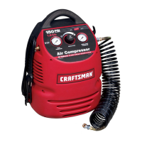
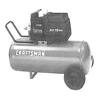
This document is an owner's manual for a Sears Craftsman Permanently Lubricated Air Compressor, models 919.156730 and 919.156830.

Function Description:

The Sears Craftsman air compressor is a single-stage, 1-cylinder unit designed to compress air for various applications. It consists of an air compressor pump, an air tank, wheels, handles, and associated controls, including an air chuck. Unlike many air compressors, this model is permanently lubricated, meaning it does not require oiling or additional lubrication, simplifying maintenance. The compressed air can be used to operate a variety of pneumatic tools and accessories such as paint spray guns, air tools, caulking guns, grease guns, air brushes, sandblasters, and for inflating tires and plastic toys, as well as spraying weed killers and insecticides. It is important to note that this model is not equipped with a pressure regulator, which is often necessary for most applications. Separate air transformers for regulation and moisture/dirt removal may be required.

Important Technical Specifications:

The manual provides detailed specifications for both models:

  • Model Numbers: 919.156730 and 919.156830
  • Horsepower: 3 HP for both models
  • Displacement CFM: 11.8 for both models
  • Bore: 2 3/8" for both models
  • Stroke: 1.35" for both models
  • Voltage-Single Phase: 120/240 volts (wired for 120V, convertible to 240V)
  • Minimum Branch Circuit Requirement: 15 amps
  • Fuse Type: "Fusetron" Type T*** (dual element time delay fuses are recommended if protected by fuses)
  • Air Tank Capacity: 15 gallons (ASME certified for model 919.156830)
  • Approximate Cut-in Pressure: 80 PSIG
  • Approximate Cut-out Pressure: 100 PSIG
  • SCFM @ 40 psig: 8.5
  • SCFM @ 90 psig: 7.0

The compressor features a pressure switch that automatically starts the motor when tank pressure drops below the "cut-in" pressure and stops it when the "cut-out" pressure is reached. A pressure release valve automatically releases compressed air from the compressor head and outlet tube when the compressor reaches "cut-out" pressure or is shut off, allowing the motor to restart freely. A safety valve is included to protect against high pressure if the pressure switch fails to shut off the compressor, "popping out" at its pre-set pressure. The tank pressure gauge indicates the reserve air pressure.

Usage Features:

  • Assembly: The manual details the steps for assembling the wheels, wheel plates, handle, rubber foot strip, and shut-off valve. Pipe sealant is required for the shut-off valve adapter threads.
  • Installation: The compressor should be located in a clean, dry, and well-ventilated area, at least 12 inches away from walls or obstructions to ensure proper cooling.
  • Electrical Connection: It requires a 3-wire extension cord with a 3-blade grounding plug and a 3-slot receptacle. Extension cords should be no longer than 50 feet and 12 gauge (AWG) or larger (10 AWG and 8 AWG may also be used; 14 or 16 AWG are not recommended) to avoid voltage drop and power loss. The compressor is designed for 120V operation but can be converted to 240V by replacing the attached three-prong 240V plug.
  • Break-In Procedure: A one-time break-in procedure is required before first use, involving running the compressor for 15 minutes with the shut-off valve open to prevent pressure build-up, then closing the valve to allow the tank to fill to cut-out pressure.
  • Operation: Before attaching air hoses or accessories, the pressure switch lever should be set to "OFF," and the shut-off valve closed. Users must check the maximum pressure rating of air tools and accessories, ensuring the outlet pressure never exceeds this rating. An air regulator is needed for items with a maximum pressure rating less than 125 PSI. The compressor should always be operated in well-ventilated areas, free of flammable vapors.
  • Safety Guidelines: Emphasizes the importance of reading safety information, recognizing DANGER, WARNING, and CAUTION symbols. Key safety points include:
    • Never touching hot parts of the compressor head to avoid burns.
    • Operating in well-ventilated areas free of flammable vapors to prevent fire or explosion, especially when spraying flammable materials.
    • Never modifying the air tank (drilling, welding, etc.) as it can cause rupture or explosion.
    • Not tampering with the safety valve or pressure switch.
    • Always wearing safety goggles or glasses when using the compressor.
    • Turning off the compressor before attaching or removing accessories.
    • Unplugging the compressor prior to maintenance or repair to prevent electrical shock.
    • Never using the compressor outdoors in the rain.
    • Never directly inhaling compressed air.
    • Reading labels and safety data for all sprayed materials and using appropriate masks/respirators.
    • Avoiding solvents like 1,1,1-Trichloroethane and Methylene Chloride with aluminum or galvanized parts in spray equipment, as they can cause explosions or corrosion.

Maintenance Features:

  • No Oil Required: This model is permanently lubricated, eliminating the need for oil changes or additions.
  • Air Filter Inspection: The air filter should be kept clean at all times. It can be pulled out, washed with mild detergent and warm water, or replaced if dirty. Operating without a clean air filter reduces compressor capacity.
  • Check Valve Inspection and Replacement: Instructions are provided for releasing air pressure, removing the shroud, outlet tube, and pressure release tube, then unscrewing the check valve for cleaning or replacement. Sealant is required for reinstallation.
  • Safety Valve Inspection: Users are instructed to occasionally pull the ring on the safety valve to ensure it operates freely. A stuck or non-smoothly operating valve must be replaced with the same type.
  • Motor: The motor has an automatic reset thermal overload protector that shuts off the motor if it overheats. The motor will automatically restart after cooling. Frequent shutdowns may indicate a voltage problem.
  • Draining Water from Air Tank: Water will condense in the air tank and must be drained regularly (at approximately 20 psi tank pressure) to prevent corrosion, weakening, and rupture of the tank. The drain cock should be opened to allow moisture to drain.
  • Troubleshooting Guide: A comprehensive guide helps diagnose and correct common issues such as excessive tank pressure, air leaks at various points (fittings, check valve, air tank, head/valve plate), knocking noise, insufficient air supply, and motor not running. It provides causes and corresponding corrections, emphasizing safety precautions like unplugging the compressor and bleeding off air pressure before attempting repairs.

Craftsman 919.156830 Specifications

General IconGeneral
BrandCraftsman
Model919.156830
CategoryAir Compressor
LanguageEnglish

Related product manuals