ENGLISH
6
it into the tool until the battery pack is firmly seated in the
tool and does notdisengage.
To remove the battery pack from the tool, press the battery
pack release button
9
and firmly pull the battery pack out
of the tool. Insert it into the charger as described in the
charger section of thismanual.
8
9
Fig.B
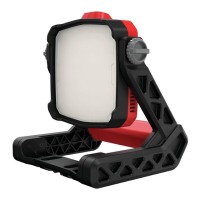
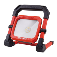
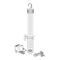
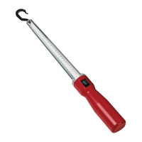
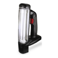
Task Light Placement (Fig. C, D)
The task light can be used one of three ways.
• On a level surface as shown in Figure C.
• Wall mounted using the keyhole slots
6
located on the
bottom of the task light as shown in Figure D. Refer to
Keyhole Slots
for further instruction.
• The light can be handheld.
Fig.C
Keyhole Slots (Fig. D)
Use the back of the keyhole slots
6
on the mounting
base as a template for the location of the mounting
screws. Mount the task light securely using drywall screws
(purchased separately) at least 1” (25.4 mm) long, with a
screw head diameter of 0.28–0.35” (7–9mm), screwed
into wood to an optimal depth leaving approximately
7/32” (5.5mm) of the screw exposed. Align the slots on the
mounting base with the exposed screws and fully engage
them in the slots.
Fig.D
6
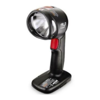
Light Levels (Fig. A)
The task light has 2 brightness levels. Continue to press the
On/Off switch
1
to cycle from OFF-HI-LO brightnesses.
On/Off Switch (Fig. A)
CAUTION: Do not stare into task light lens. Serious
eye injury couldresult.
To turn the task light on, press the On/Off switch
1
.
To turn the task light off, press the On/Off switch until the
light goes out.
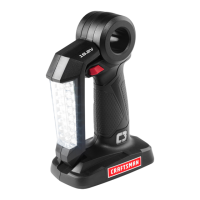
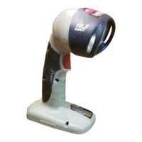
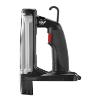
Pivoting the Light Housing (Fig. E)
The task light housing
3
can be pivoted to different
positions within the 360° pivotrange.
1. To pivot the task light housing first loosen the pivot
knobs
2
.
2. Rotate the task light housing to your desired position.
Tighten the pivot knobs.
.
Fig.E
2
3
MAINTENANCE
WARNING: To reduce the risk of serious personal
injury, turn unit off and before making any
adjustments or removing/installing attachments
or accessories. An accidental start up can
causeinjury.