A .................amperes
W ................watts
or AC ....alternating current
or AC/DC alternating or direct
current
................ Class II Construction (double
insulated)
n
o
................no load speed
n ..................rated speed
................earthing terminal
...............safety alert symbol
...............visible radiation
............... wear respiratory protection
............... wear eye protection
............... wear hearing protection
............... read all documentation
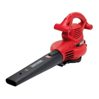
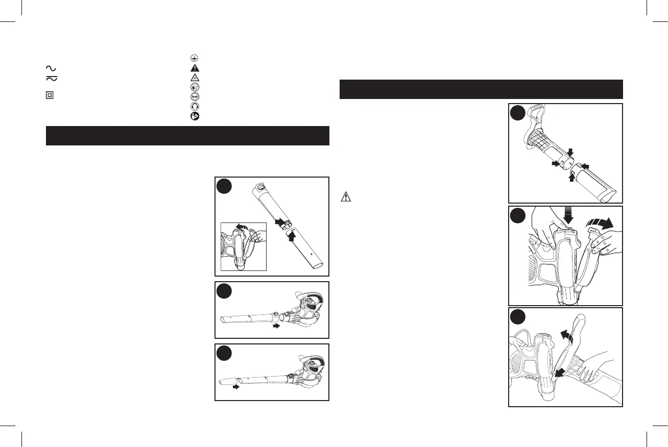
BLOWER MODE ASSEMBLY
NOTE: Ensure the blower is switched off and disconnected from the
power supply before attaching or removing the blower tubes. The tube
assembly must be assembled to the housing beforeuse.
TUBE ASSEMBLY
(FIGURES A, B, C)
• Ensure grill cover is attached to the
power head. If not, attach cover as
shown in the inset of figure 1. NOTE:
Unit will not operate in blow mode
without grill cover in place. Align the
upper and lower tubes as shown in
figureA.
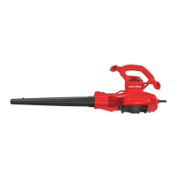
• Push the lower tube firmly into the
upper tube, until the tubes click
intoplace.
• Blow tubes must be assembled to the
power head beforeuse.
• Never operate without both lower and
upper tubesassembled.
• In the interest of safety, it is not
intended for the tubes to be separated
onceassembled.
• Push the tube assembly onto the
power head until it is in the fully locked
position (figureB).
5
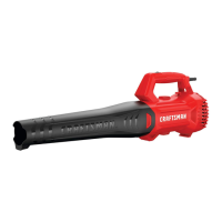
• Use the air concentrator attachment to target air flow to a tighter area.
Add the attachment to the assembly as shown in figure C. Push on
until hole in tab engages raised post ontube.
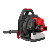
VACUUM MODE ASSEMBLY
VACUUM TUBE ASSEMBLY
(FIGURES D, E, F)
NOTE:
Ensure the vacuum is switched off
and disconnected from the power supply
before attaching or removing the vacuum
tube. The vacuum tube and collection
bag must be assembled to the housing
before use. The vacuum tubes must be
assembled together beforeuse.
CAUTION:
CUT HAZARD.
Ensure
the tube assembly is securely seated and
latched intoposition.
NOTE: This interlock will connect the
electric circuit automatically and the unit
willoperate.
• Vacuum tubes must be assembled
together beforeuse.
• Align the notches and the triangles on
upper and lower tubes. (figure D)
• Push the lower tube firmly into the
upper tube, until the triangles click into
place. (Never operateapart).
• In the interest of safety, it is not
intended for the tubes to be separated
onceassembled.
• Remove the fan cover from the bottom
of the power head by pressing the
spring loaded release button (located
on the back of the power head) and
pulling the cover off (figureE).
• Attach the vacuum tube assembly to
A
B
C
D
D
E
F