ENGLISH
6
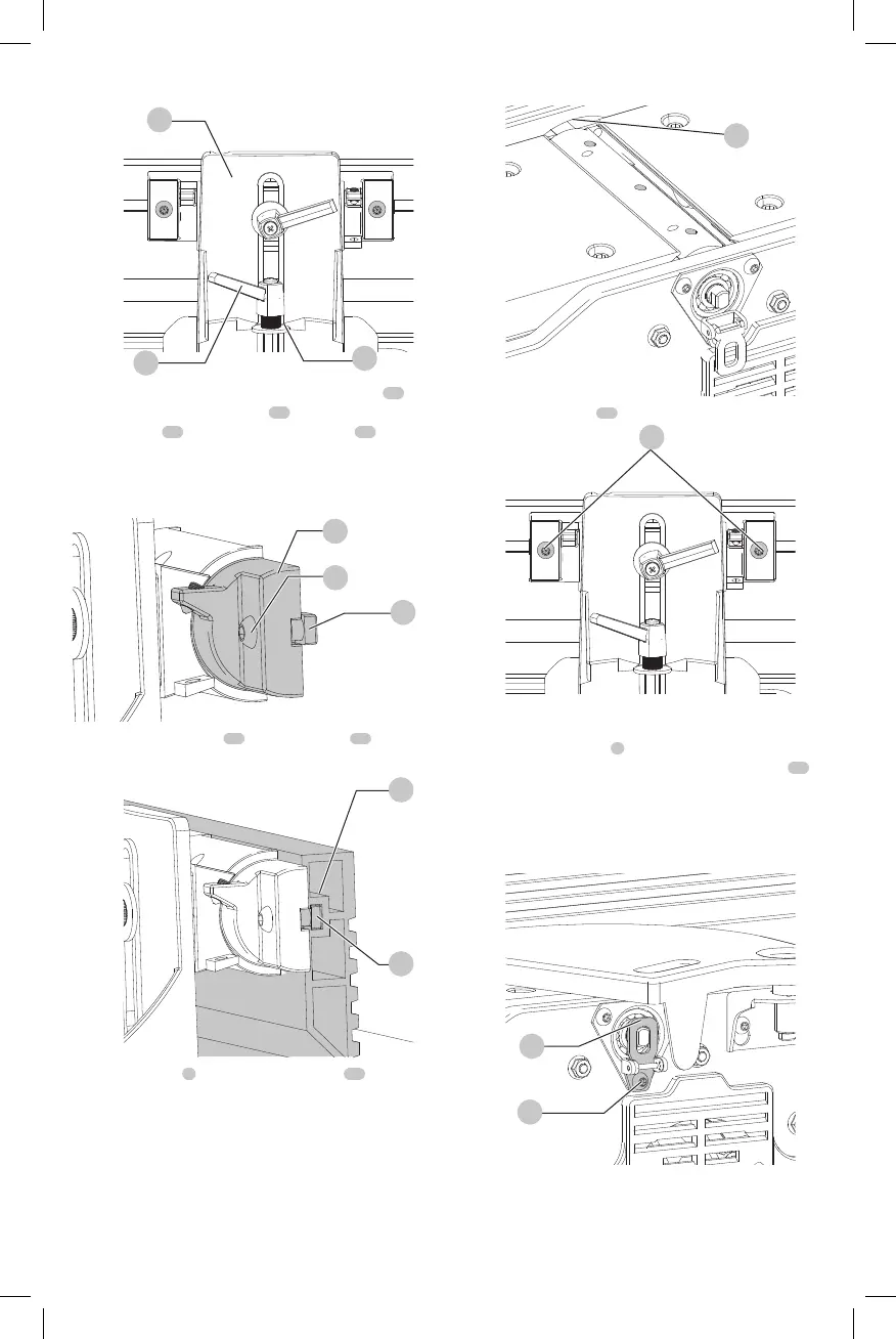
Fig.F
3
19
13
3. Insert a M6 x 1 mm x 16 mm button head screw
16
through fence tilting bracket
15
and thread a M6 x 1
square nut
17
onto threaded end of screw
16
. DO NOT
COM PLETE LY TIGHTEN SCREW AT THIS TIME. Assemble
screw and square nut to opposite end of tilting bracket
in the samemanner.
15
Fig. G
16
17
4. Slide groove of fence
18
over square nuts
17
.
Fig.H
18
17
5. Position fence
1
so that rounded section
45
on
bottom of fence is over cutterheadopening.
Fig.I
45
6. Tighten two screws
16
using included hexwrench.
Fig.J
16
Cutterhead Lock (Fig. K)
Assemble cutterhead lock
4
to the front side of the jointer
base, using the M6 x 1 mm x 12 mm button head screw
21
.
NOTE: The cutterhead lock is to be engaged with the
cutterhead shaft only when setting knives. All other
times, the cutterhead lock should be disengaged from
thecutterhead.
Fig.K
21
4
 Loading...