11
ASSEMBLY
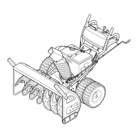
Overhead Chute Control (w/ Chute Control Rod)
Figure 12
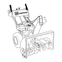
1. Remove wing nut and hex screw from chute control head and clevis pin and
cotter pin from chute support bracket. Position chute assembly (forward-
facing) over chute base. See Figure 13.
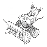
Chute Support Bracket
Chute Control Head
Chute
Chute Base
Figure 13
2. Place chute assembly onto chute base and secure chute control head to chute
support bracket with clevis pin and cotter pin removed in Step 1. See Figure
14.
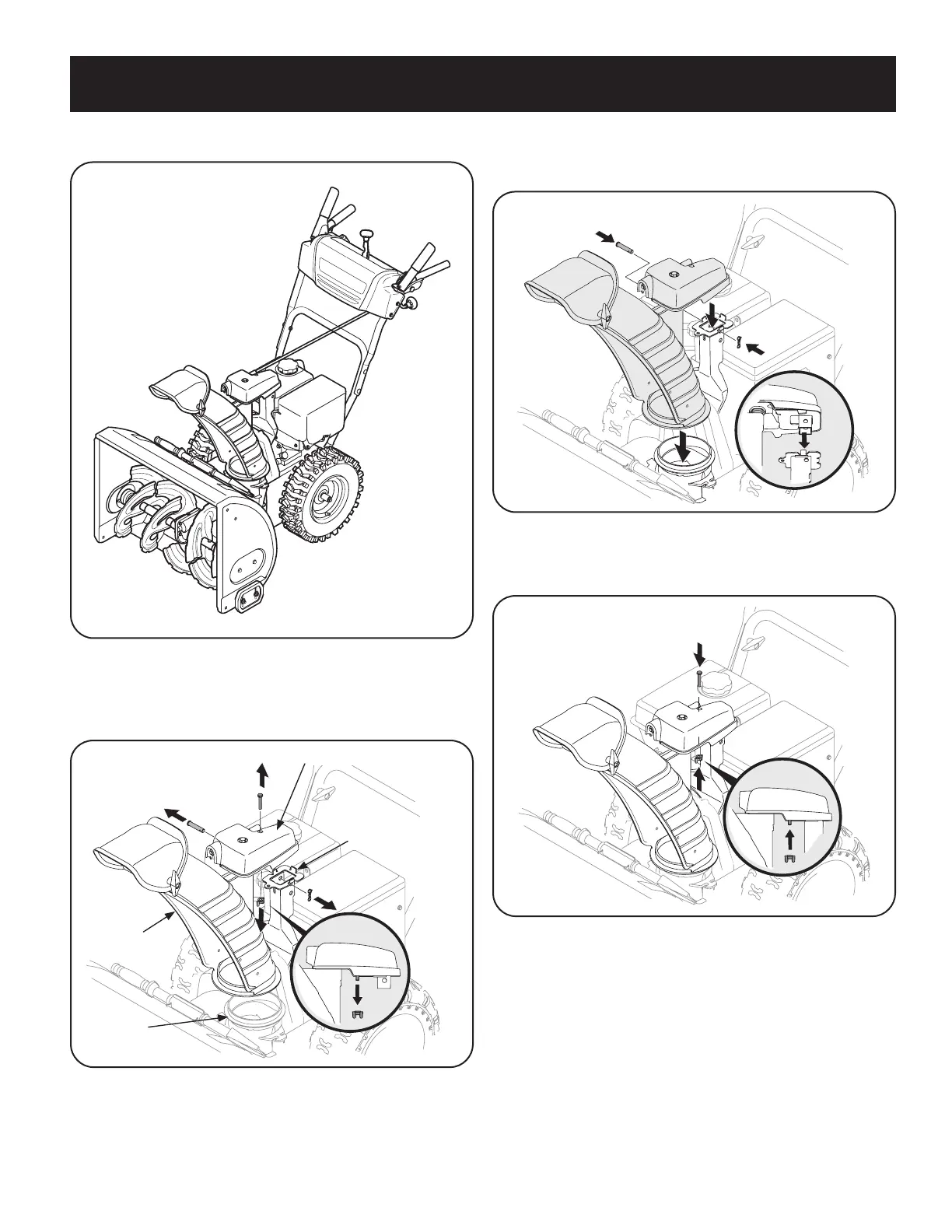
Figure 14
3. Finish securing chute control head to chute support bracket with wing
nut (a) and hex screw (b) removed in Step 1. See Figure 15.
Figure 15
 Loading...