Do you have a question about the Craftsman SB270 and is the answer not in the manual?
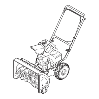
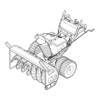
Attach wing knobs and carriage bolts from the lower handle, pivot the upper handle, and reattach knobs to secure.
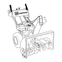
Place the chute handle on the lower chute, aligned in the channel and snapped into place.
Remove screws from chute base, position chute assembly, and secure with screws.
Attach wing knob and rope guide to upper handle, route starter rope, and tighten knob.
Add oil to the oil fill and fill the fuel tank with clean, fresh gasoline.
Insert the key into the key switch until it snaps into place.
Move the choke control into the Choke position.
Connect an extension cord to the electric starter outlet and plug into a receptacle.
Push the primer three times.
Push starter button, move choke to Run when engine starts, and disconnect power cord.
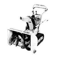
This document provides a "Fast Start Guide" for the assembly and engine start of a Craftsman snow thrower, designed to help users quickly set up and operate their new equipment. The guide emphasizes safety by instructing users to "READ AND UNDERSTAND ALL INSTRUCTION, WARNING, AND DANGER LABELS" and to refer to the full operator's manual and engine manual for comprehensive information and safe operation practices.
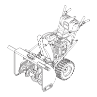
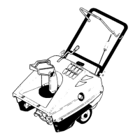
The assembly process is broken down into four main steps, focusing on the handle, chute, and starter rope.
Handle Assembly:
Chute Handle Installation:
Chute Assembly Installation:
Starter Rope and Rope Guide Installation:
The "Fast Start Guide - Engine Start" section details the steps required to prepare the snow thrower for operation, including adding fluids and using the electric or manual start system.
Fluid Addition (Oil and Fuel):
Key Insertion:
Choke Control:
Electric Start Connection:
Priming the Engine:
Engine Starting Procedure:
While primarily a quick start guide, several features imply aspects of usage and maintenance:
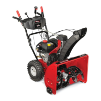
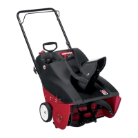
In summary, this Craftsman snow thrower is designed for efficient snow removal, featuring a user-friendly assembly process, convenient starting options (electric and manual), and clear instructions aimed at ensuring safe and effective operation. Its design implies considerations for storage, ease of use, and a structured approach to maintenance through comprehensive documentation and support.
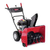
| Engine Type | 4-cycle OHV |
|---|---|
| Clearing Width | 27 inches |
| Drive System | Self-propelled |
| Engine | 208cc |
| Stages | Two-stage |
| Intake Height | 20 inches |
| Starter | Electric Start |
| Tire Size | 15 x 5 inches |
| Type | Two-stage |
| Drive Type | Wheel |