6
Assembly Instructions
You should have three boxes for a complete unit - (Figure 1). Contents are as follows:
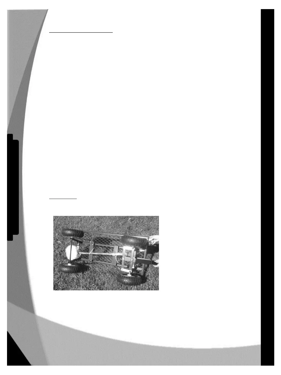
• 4 wheel cart - (Figure 2)
• Handle assembly (handle, two spacers, bolt, lock nut) – (Figure 3.)
• 2 Aluminum support pipes – (Figure 4.)
• Manifold assembly w/ 6 hoses/ 6 valves - (Figure 5)
• Cabinet– (Figure 6.)
• Cabinet mounts (attached to back of cabinet) – (Figure 7)
• Zip Ties – (Figure 8)
• 4 bolts, and 4 nuts (in zip closed plastic bag) – inside the cabinet - (Figure 9)
• Allen wrench – (Figure 10)
• Aluminum support pipe mount – (Figure 11)
• Tank Drain– (Figure 12)
• 2 tie-down straps – (Figure 13)
• Battery charger – (Figure 14)
• Optional Charger cord – (Figure 15)
• Battery and harness – (Figure 16)
• Instructions
• Fuse (extra inside cabinet door)
Additional tools needed: 2- 7/16" open end wrenches, large adjustable wrench, and a regular
screwdriver.
Please read these instructions carefully before attempting assembly.
****IMPORTANT: Some steps require you to tighten a fitting hand tight only. This is to avoid
damage to the plastic components. Tightening a plastic connection with a wrench will not
ordinarily stop a leak, but it will almost always cause damage. Cramer Products will not replace
under warranty any parts damaged by over tightening.****
Cart Handle
• Remove and unwrap handle assembly from underneath cart.
6
Parts and Assembly
PowerFlo ™ - Owner's Manual
 Loading...