PARTSSHOWN IN PICTURE A:
1. Motor and chain
2. Tracks, 3 pcs
3. Track joints, 2 pcs
4. Control unit with lamp
5. Chain, 3 part
6. Mains supply cable
7. Single-core, wallswitch cable
8. Three-core, wall switch cable
9. Wall switch
10. Rear switch, marked, "H"
11. Front switch, marked, "V"
12. Roof bracket
13. Pulley arm, door bracket, bolt, retaining clip
14. Lintel fitting
15. Chain bolt, spring, washer, nut
16. Angle iron, screws, plugs
17. Emergency unlocking device
18. Lamp cover
19. Pulling force adjustment
20. Remote control
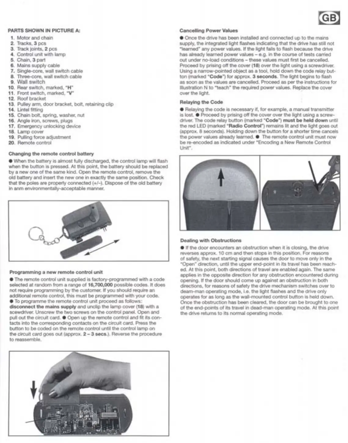
Changing the remote control battery
. When the battery is almost fully discharged, the controllamp will flash
when the button is pressed. At this point, the battery should be replaced
by a new one of the same kind. Open the remote control, remove the
old battery and insert the new one in exactly the same position. Check
that the poles are properly connected (+/-). Dispose of the old battery
in anm environmentally-acceptable manner.
Program min g a new remote control unit
. The remote control unit supplied is factory-programmed with a code
selected at random from a range of 16,700,000 possible codes. It does
not require programming by the customer. If you should require an
additional remote control, this must be programmed with your code.
. To programme the remote control unit proceed as folIows:
disconnect the mains supply and unclip the lam p cover (18) with a
scewdriver. Unscrew the two screws on the control panel. Open and
pull out the circuit card. . Open up the remote control and fit its con-
tacts into the corresponding contacts on the circuit card. Press the
button to be coded an the remote control until the controllamp on
the circuit card goes out (approx. 2 - 3 secs.). Reverse the procedure
to reassemble.
@~
Cancelling Power Values
. Once the drive has been installed and connected up to the mains
supply, the integrated light flashes indicating that the drive has still not
"Iearned" any power values. If the light fails to flash because the drive
has already learned power values - e.g. in the course of tests carried
out under no-load conditions - these values must first be cancelled.
Proceed by prising off the cover (18)over the light using a screwdriver.
Using a narrow-pointed object as a tool, hold down the code relay but-
ton (marked "Code") for approx. 3 seconds. The light Qeginsto flash
as soon as the values are cancelled. Proceed as per the instructions for
Illustration N to "teach" the required power values. Replace the cover
over the light. '
Relaying the Code
. Relaying the code is necessary if, for example, a manual transmitter
is lost. . Proceed by prising off the cover over the light using a screw-
driver. The code relay button (marked "Code") must be held down until
the red LED (marked "Radio Control") remains lit and the light goes out
(approx. 8 seconds). Holding down the button for a shorter time cancels
the power values already learned.. The remote control unit must now
be re-encoded as indicated under "Encoding a New Remote Control
Unit".
Dealing with Obstruction s
. If the door encounters an obstruction when it is closing, the drive
reverses approx. 10 cm and then stops in this position. For reasons
of safety, the next starting signal causes the door to move only in the
"Open" direction, until the upper end-point in its traveI has been reach-
ed. At this point, both directions of traver are enabled again. The same
applies in the opposite direction for any obstruction encountered during
opening. If the door should come up against an obstruction in both
directions, for reasons of safety the drive mechanism switches over to
deam-man operating mode, Le.the light flashes and the drive only
operates for as long as the wall-mounted control button is held down.
Once the obstruction has been cleared, the door can be brought to one
of the end-points of its travel in dead-man operating mode. At this point
the drive returns to its normaloperating mode. .



 To Next Page
 Loading...