4
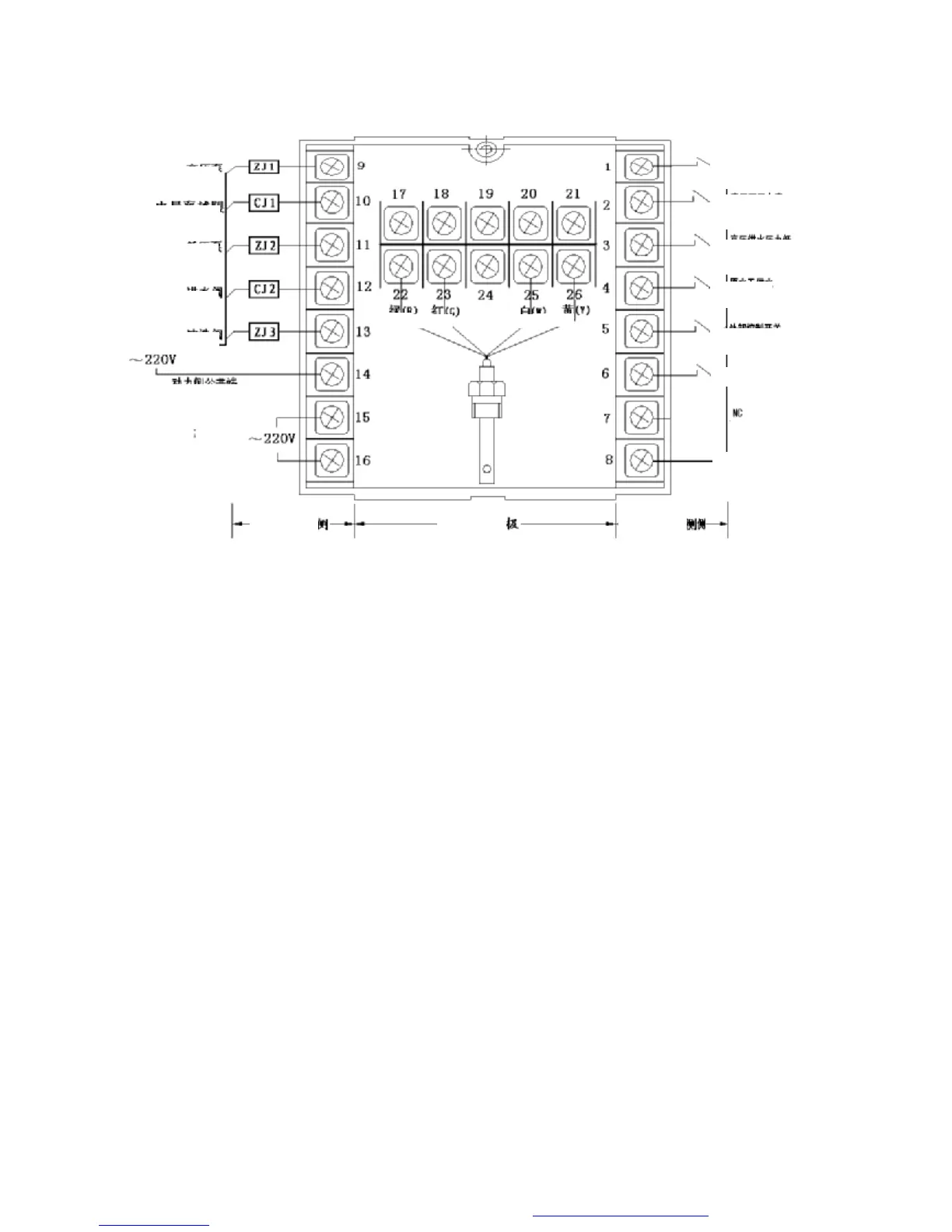
5 Rear Panel Illustration
Since small relay is used in the controller, when driving larger inductive load, intermediate relay or
contactor must be used, direct driving is not allowed.
Note: ZJ—intermediate relay CJ---magnetic contactor (refer to appendix for type selection)
The rear connecting terminals are shown in the diagram, the definitions of the terminals are:
Terminals from up to down on the left:
9----output contact terminal of high pressure pump on/off control (normally open, passive)
10---contact terminal of conductivity over limit control (normally open, passive)
11--- output contact terminal of low pressure pump on/off control (normally open, passive)
12--- output contact terminal of inlet magnetic valve on/off control (normally open, passive)
13--- output contact terminal of flush magnetic valve on/off control (normally open, passive)
14---a common terminal used jointly by the control signals of terminal 9, 10, 11, 12 and 13.
15, 16---connection terminal of 220V commercial power.
Terminals from up to down on the right:
1---input terminal of high water level detection switch of pure water tank (normally open, close in
case of low water level of pure water tank)
2---input terminal of booster pump over pressure detection switch (normally close, switch off in case
of over pressure)
3---input terminal of insufficient low pressure detection switch (normally open, close at a preset
pressure)
4---input terminal of raw water low feed detection switch (normally open, close when water exists)
If your system has a raw water tank as shown in Fig. 1-A, this terminal is connected to the
normally open contact of the raw water tank low level limit, it will close when water exists; if your
 Loading...