v. 2.3 5/20/97 B1000022
Crest Audio Inc.
100 Eisenhower Dr., Paramus NJ 07652 USA
TEL: 201.909.8700 FAX: 201.909.8744
http://www.crestaudio.com
Printed in USA
† Power figures are watts per channel, both channels driven, 1kHz, 1% THD+N. * 3-Year Warranty with 2 additional years is Registration Card is sent to Crest Audio. (USA, UK, Canada, and
many other countries). Crest Audio reserves the right to make improvements in manufacturing or design which may affect specification. Crest Audio specification literature is available in
downloadable PDF format; visit our website at: http://www.crestaudio.com. ©1997 Crest Audio Inc.
400 Watts
750 Watts
1000 Watts
1500 Watts
2000 Watts
70.7V
200V
10Hz-20kHz, -3dB @ 165kHz
20Hz-20kHz
ACL, IGM, AutoRamp, short circuit,
DC voltage, turn-on/off transient, current inrush,
sub/ultrasonic input.
<1.0%
<0.05%
>1000:1
> - 64dB
1.4V
X38.6
>20kΩ/>10kΩ
-105 dB
> - 60 dB
H
TRS (tip +) & Barrier Strip
5-way binding posts or Speakon
(market dependent)
50,000 µF
100V-240V, 50-60Hz
1.8A
4.3A
8.5A
21.0A
3100 BTU/hr
4400 BTU/hr
Front to Side via one 110 CFM, 2-Speed AC fan
Front Panel: 2 attenuators, magnetic circuit
breaker/power switch.
Rear Panel: mode select switch.
20-segment signal meter w/peak hold, Protect,
Active, Active Clip Limiting (ACL)
14 gauge steel
5.25" x 19" x 13.33" / 133 x 483 x 339mm
49 lbs. / 22.2 kg., 46 lbs / 20.9 kg.
5 years*
8Ω Stereo Power †
4Ω Stereo Power †
2Ω Stereo Power †
8Ω Bridged Power †
4Ω Bridged Power †
Max RMS Output Voltage
(each channel)
Peak Output Voltage (each channel)
Frequency Response (+0/-0.3dB, 1W/8Ω)
Power Bandwidth (Rated power at 4Ω, 1% THD+N)
TourClass Protection
THD+N
(rated power at 4Ω, 1kHz)
SMPTE IMD (rated power at 8Ω, 60Hz & 7kHz)
Damping Factor (10-400Hz at 8Ω)
Input CMRR (1 kHz)
Input Sensitivity (rated power at 8Ω)
Voltage Gain
Input Impedance
(balanced/unbalanced)
Hum & Noise (“A” weighted, full power at 4Ω)
Crosstalk (“A” weighted, full power at 4Ω)
Class
Input Connectors
(per channel)
Output Connectors (per channel)
Filter Storage
Power Supply
(factory configured)
Idle Current Draw (120V)
1/8 Power Curr. Draw (typical music, 120V/4Ω)
1/3 Power Curr. Draw (continuous music, 120V/4Ω)
Max Curr. Draw (circuit breaker rating, 120V/4Ω)
Thermal Emissions (1/8 Power, 4Ω)
Thermal Emissions (1/3 Power, 4Ω)
Cooling
Controls
LED Indicators
(per channel)
Construction
Dimensions (Height x Width x Depth)
Gross Weight, Net Weight
Warranty
Architect’s & Engineer’s Specifications
The power amplifier shall have two channels. Each channel shall deliver a
minimum of 400 watts at 8 ohms, 750 watts at 4 ohms and 1000 watts at 2
ohms, 1kHz, 1% THD+N. In bridged mono mode, it shall deliver 1500
watts at 8 ohms and 2000 watts into 4 ohms, 1kHz, 1% THD+N.
The amplifier shall have circuitry to protect itself and the speaker load
from output short circuits, DC voltage on outputs, and thermal overload.
The amplifier shall include circuitry to gradually increase gain to attenua-
tor setting levels when the amplifier is turned on, and circuitry for imped-
ance sensing and active clip limiting.
The amplifier shall be front-to-side cooled, with a two-speed AC fan.
The amplifier shall have a voltage gain of X38.6 with an input sensitivity
of 1.4V for rated power at 8 ohms. THD+N shall be less than 1.0% at 4Ω,
1kHz. The hum and noise level shall be 105 dB below rated output, “A”
weighted. SMPTE IMD shall be less than 0.05%, rated power at 8Ω, 60Hz
and 7kHz. The amplifier shall have a class H output stage. The frequency
response shall be greater than 10Hz-20kHz, +0/-0.3dB, 1W/8Ω.
The amplifier shall operate at 100V-240V, 50-60 Hz AC (configured at
factory). Maximum current draw shall not exceed 21 amperes at 120VAC,
(circuit breaker limited), with both channels driven continuously into a 4
ohm resistor.
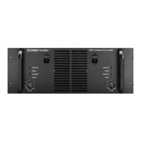
Front panel mounted attenuators shall be recessed and detented. Front
panel indicators shall include an “Active” LED, a “Protect” LED and a
20-segment LED signal level meter for each channel, which includes an
ACL LED. The amplifier shall have a combination power switch/magnetic
circuit breaker fitted on the front panel.
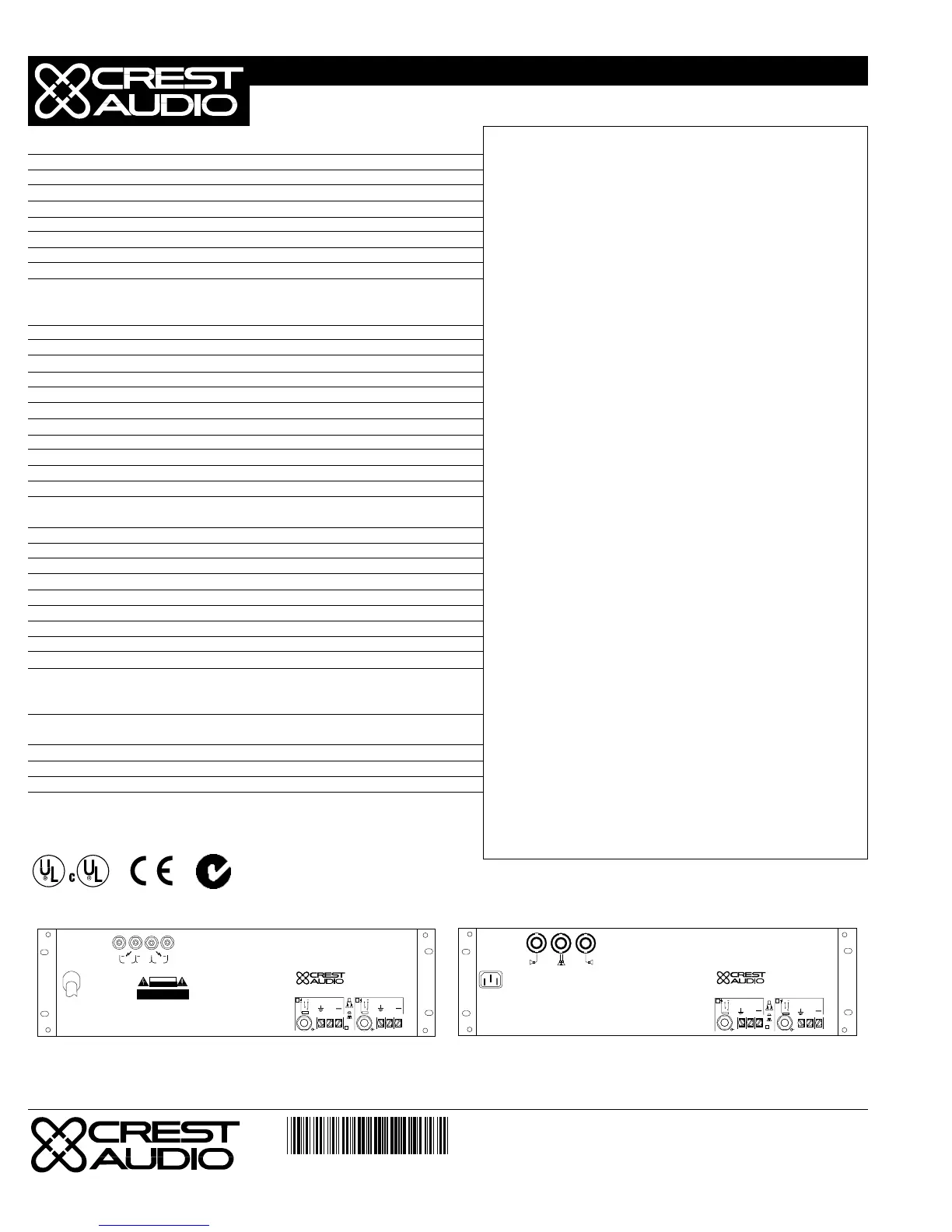
A rear panel Bridge/Stereo mode select switch shall be provided. Rear
panel input connectors shall be an actively balanced TRS (tip +), and bar-
rier strip for each channel. Output connectors shall be Speakon or 5-way
binding posts (market dependent). Rear mounting ears shall be provided.
A rear-panel IEC AC mains socket or single AC mains cord having an
appropriate AC plug for the intended operating voltage shall be provided
(market dependent).
The packaging of the amplifier shall allow for standard rack mounting
without requiring space between similar units. Optional rack mount han-
dles shall be available. Dimensions shall be 5.25" (133mm) high x 19"
(483mm) wide x 13.33" (339mm) deep. The amplifier shall have a net
weight of 46 lbs. (20.9 kg). The amplifier shall be designated the Crest
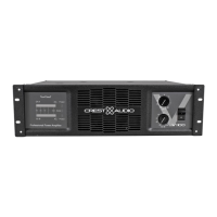
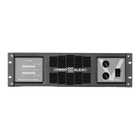
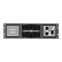
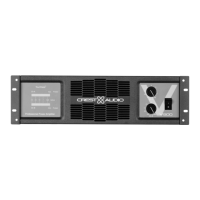
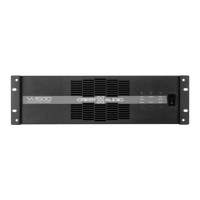
Audio model V1500.
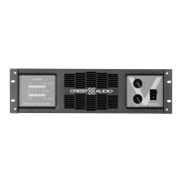
V1500 POWER AMPLIFIER
SPECIFICATIONS
Serial Number
Designed & manufactured in the USA by:
Crest Audio Inc.
100 Eisenhower Dr.
Paramus New Jersey, 07652 USA
A+B
A B
+
+
B
A
+
+
+
+
Ch.B
Bridge
Ch.A
Output Output
+
RISK OF ELECTRIC SHOCK
DO NOT OPEN
CAUTION
AVIS : RISQUE DE CHOC ÉLECTRIQUE—NE PAS OUVRIR
WARNING TO REDUCE THE RISK OF FIRE OR ELECTRIC SHOCK DO NOT
EXPOSE THIS EQUIPMENT TO RAIN OR MOISTURE.
ATTENTION! POUR ÉVITER LE RISQUE D'INCENDIE OU DE CHOC
ÉLECTRIQUE, NE PLACEZ PAS CET APPAREIL SOUS LA PLUIE OU Á
L'HUMIDITÉ
643-210
CLASS 2 WIRING MAY BE USED
A+B
Serial Number
Designed & manufactured in the USA by:
Crest Audio Inc.
100 Eisenhower Dr.
Paramus New Jersey, 07652 USA
+
B
+
A
A B
NL4FC
B
A
A+B
643-016
+
+
Rear View, Binding Post Version
Rear View, Speakon Version (not available in North America)
B1000022
 Loading...