Professional Audio Distribution Processor Crestron CNX-PAD8A
CNX-PAD8A Ports
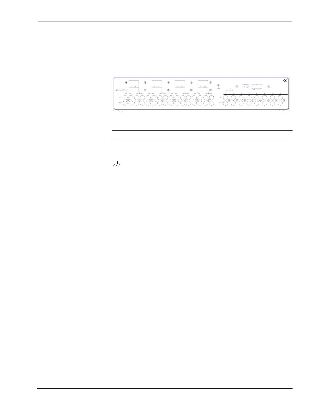
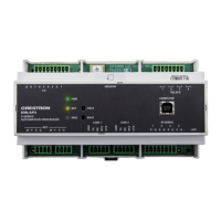
A number of ports are provided on the back of the CNX-PAD8A. Each has a silk-
screened label. Refer to the illustration and descriptions below.
CNX-PAD8A Ports
USA07647.J.NROC K LEIGH,INC .ELECT RO INCS
CR SETRON
NET
NOTE: There are no RJ-11 connectors on this product.
Use the supplied 4-pin network connector as described in "Network Wiring" on page
9 and connect the control system and other peripherals to this port.
(Chassis Ground)
Use this chassis screw to connect the audio source(s) common ground(s) to the
CNX-PAD8A.
SOURCES 1 - 8
Each of the eight sets of four RCA connectors is used to connect the independent
audio sources to the CNX-PAD8A. Of each set, two of the connectors are used for
the left and right audio channels and the remaining two connectors are parallel stereo
loop-throughs.
The eight rectangular blanks (labeled 1-2, 3-4, 5-6, and 7-8) are used with the
optional Audio Switcher Bussing Kit. The kit contains a printed circuit board with
eight connectors that when installed, is used to daisy-chain three additional
CNX-PAD8As to provide up to a total of 32 room outputs. Refer to the latest
revision of the CNX-ASBK Operations & Installation Guide (Doc. 8143) for further
information.
ROOMS 1 – 8
These eight pair of RCA jacks output the pre-amplified audio to the corresponding
room(s) amplifier(s). Each room output contains left and right audio channels.
4 • Professional Audio Distribution Processor: CNX-PAD8A Operations Guide – DOC. 8174