Professional Automation Computer Crestron PAC2
NOTE: Since the plug on the power supply cord is used to disconnect power from
the unit, the socket-outlet shall be installed near the equipment and shall be easily
accessible.
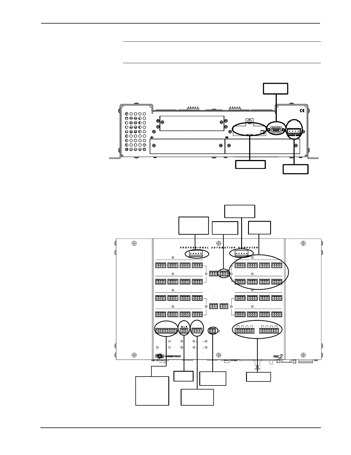
Hookup Connections for the 2-Series Automation Control System (front panel)
MEMORY
EXPANSION
S3 Z-BUS
COMPUTER
NET
24 Y Z G
For optional compact
flash memory card
To any
Cresnet device
To serial port on
PC using DB9
RS-232 cable
Hookup Connections for the 2-Series Automation Control System (top panel)
To CLX-series
module (for single
and double wide
CAEN)
To 8 Cresnet
network
devices
24 VDC to hub
from internal or
external power
To controllable
devices
From device
outputs
-contact closures
-solid state closures
To override
switch
To 2-Series
Control System
for Backup Cresnet
and Power
To 2-Series
Control System
(I/O port)
To controllable
devices
To CLX-series
module (for double
wide CAEN)
24 Y Z G 24 Y Z G 24 Y Z G 24 Y Z G
24 Y Z G 24 Y Z G 24 Y Z G 24 Y Z G
24 Y Z G 24 Y Z G 24 Y Z G 24 Y Z G
24 Y Z G 24 Y Z G 24 Y Z G 24 Y Z G
24 Y Z G 24 Y Z G 24 Y Z G 24 Y Z G
24 Y Z G 24 Y Z G 24 Y Z G 24 Y Z G
24 Y Z G 24 Y Z G 24 Y Z G 24 Y Z G
24 Y Z G 24 Y Z G 24 Y Z G 24 Y Z G
S4
I/O
OVER
RIDE
BACKUP
NET INPUT
24 Y Z G
1 2 3 4 5 6 7 8 G
FAULT
F G
1 2 3 4 5 6 7 8
S5
RELAY OUTPUT
RIGHT
LEFT
NET C
NET D
NET G
NET H
NET A
NET B
NET E
NET C
POWER
3 4
G
INT
EXT
G
INT
EXT
PWR
HW-R
SW-R
NET
ERR
LNK
ACT
LAN A LAN B
POWER
1
2
G
INT
EXT
G
INT
EXT
18 • Professional Automation Computer: PAC2 Operations Guide – Doc. 5941