EasyManua.ls Logo

Crossfire TEK75.2 User Manual

Default Icon
8 pages
To Next Page IconTo Next Page
Page #1 background imageLoading...
Page #1 background image
Features
Features
Class AB Circuitry
Fully 2 Ohm Stable Stereo Operation
Military Spec. Audiophile Grade Components
High Efficiency MOSFET Power Supplies
-Multi-stranded power torroid
-IRFZ44 MOSFET Transistors
Efficient Bipolar Output Transistors
Oversized Capacitor Bank
Wire Free PC Board Layouts
Gold Plated Input and Output Connectors
Variable Highpass and Lowpass Electronic Crossovers
Simultaneous Mono/Stereo Operation Capability
Internally Bridgeable
5 Way Protection Circuitry
Soft Start, On/Off Circuitry
High Level Inputs
Two Year Limited Warranty
MODEL: TEK35.2 TEK50.2 TEK75.2 TEK100.2 TEK150.2 TEK35.4 TEK50.4 TEK400.1
RMS Power/4 ohms 35W x 2 50W x 2 75W x 2 100W x 2 150W x 2 35W x 4 50W x 4 200 x 1
Bridge Power, Max. 140w x 1 200W x 1 300W x 1 400W x 1 600W x 1 150W x 2 200W x 2 400 x 1
T.H.D. 0.02% 0.02% 0.02% 0.02% 0.02% 0.02% 0.02% 0.02%
Bandwidth + 3dB 5Hz-38KHz 5Hz-38KHz 5Hz-38KHz 5Hz-38KHz 5Hz-38KHz 5Hz-38KHz 5Hz-38KHz 5Hz-38KHz
Signal To Noise >93dB >95dB >97dB >97dB >100dB >95dB >95dB >94dB
Damping Factor >150 >200 >200 >200 >300 >150 >150 >310
Separation 60dB 60dB 62dB 62dB 68dB 61dB 61dB NA
Input Sensitivity 180mV-4V 180mV-4V 180mV-4V 180mV-4V 180mV-5V 180mV-4V 180mV-4V 265mV-5V
Input Impedance 20Kohm 20Kohm 20Kohm 20Kohm 20Kohm 20Kohm 20Kohm 20Kohm
Power Fuse 15 Amp 20 Amp 25 Amp (2)25 Amp (2)30 Amp 25 Amp (2)20 Amp (2)25 Amp
Dimensions W: 9.3 IN 9.3 IN 9.3 IN 9.3 IN 9.3 IN 9.3 IN 9.3 IN 9.3 IN
H: 2.1 IN 2.1 IN 2.1 IN 2.1 IN 2.1 IN 2.1 IN 2.1 IN 2.1 IN
L: 8.35 IN 10.32 IN 11.5 IN 13 IN 15 IN 11.5 IN 11.5 IN 11.5 IN
CROSSOVER
Variable Low Pass 50-150Hz 50-150Hz 50-150Hz 50-150Hz 50-150Hz 50-150Hz 50-150Hz 50-150Hz
Variable High Pass 50-150Hz 50-150Hz 50-150Hz 50-150Hz 50-150Hz 50-150Hz 50-150Hz 50-150Hz
X-Over Slope 12dB 12dB 12dB 12dB 12dB 12dB 12dB 12dB
45hz BOOST Yes Yes Yes Yes Yes No No No
All specifications are with 12.5 volts DC. Typical output with 14.4 volts DC is 20% higher.
Specifications
Specifications
The quality of installation may affect the performance and reliability of your Crossfire product. If you have any doubts or questions regarding installation, you may
wish to contact your authorized Crossfire dealer. Remember to follow all wire and fuse requirements suggested in this manual. Warranty may void if proper
installation technique is not used (refer to warranty section in the rear of this manual).
IMPORTANT
IMPORTANT
Please read all instructions before installation!
Appropriate mounting is very important for prolonged life expectancy of any amplifier. Select a location of applicable space that allows sufficient airflow and
provides protection from moisture. Keep in mind that an amplifier should never be mounted upside down. Upside down mounting will compromise heat dissipation
through the heatsink and will engage the thermal protection circuit much sooner. Excessive heat can shorten your amplifier's life. To maximize heat dissipation, be
sure to leave at least 2.5 inches of clearance around the amplifier. Fans should be used in correspondence with an escape duct for heat when mounting the amplifier
in an enclosed or restricted area.
Avoid slipping and scratching your new Crossfire amplifier by pre-drilling the mounting holes with either a 1/8" or 3mm diameter drill bit when using the screws
supplied in the accessory kit. Always investigate the mounting area thoroughly for electrical wires, vacuum lines, and brake or fuel lines before you start to prevent any
potentially expensive mistakes.
MOUNTING
MOUNTING
Correct Mounting
O
Heat is lifted from the amplifier heatsink.
LOW IN
R
L
LEVEL
ON OFF
FREQ
HPF FULL LPF
POWER
50Hz 150Hz
HIGH IN
L R
CROSSOVER BOOST
Heat is trapped inside the amplifier, shortening
the life of the electronic components.
x
Incorrect Mounting
LOW IN
R
L
LEVEL
ON OFF
FREQ
HPF FULL LPF
POWER
50Hz 150Hz
HIGH IN
L R
CROSSOVER BOOST
TEK AMPLIFIERS
TEK AMPLIFIERS
TEK AMPS

Other manuals for Crossfire TEK75.2

Question and Answer IconNeed help?

Do you have a question about the Crossfire TEK75.2 and is the answer not in the manual?

Crossfire TEK75.2 Specifications

General IconGeneral
Channels2
RMS Power @ 4 Ohms75W x 2
RMS Power @ 2 Ohms100W x 2
Bridged RMS Power @ 4 Ohms200W x 1
S/N Ratio>90dB
Crossover Frequency50Hz - 250Hz
Bass Boost0dB - 12dB

Summary

Specifications

IMPORTANT

Please read all instructions before installation!

Essential pre-installation guidance for optimal performance and warranty adherence.

MOUNTING

Incorrect Mounting

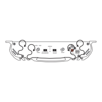
Illustrates poor mounting practices that can lead to heat buildup and component damage.

Correct Mounting

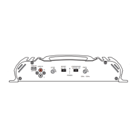
Demonstrates proper amplifier placement to ensure adequate airflow and efficient heat dissipation.

Power Connections

POWER WIRE & FUSE

Details recommended wire gauges and fuse ratings for safe and efficient power supply.

POWER

Instructions for connecting the main power wire directly to the battery for amplifier operation.

GROUND

Guidelines for establishing a solid ground connection for amplifier stability and performance.

REMOTE TURN-ON

SPEAKER OUTPUT

LOAD

Information on speaker impedance requirements for optimal amplifier performance and protection.

WIRING

Advice on selecting appropriate speaker wire and routing it safely to prevent damage.

WIRE DIAGRAMS

TWO CHANNEL AMPLIFIERS

Two Channel Operation (stereo)

Wiring diagram illustrating stereo connection for two-channel amplifiers.

Three Channel Operation (stereo/mono)

Wiring diagram for connecting speakers in stereo and mono modes with three-channel amps.

FOUR CHANNEL AMPLIFIERS

Four Channel Operation (stereo)

Wiring diagram for stereo speaker connections on four-channel amplifiers.

Three Channel Operation (stereo & mono)

Wiring diagram for stereo/mono speaker connections on four-channel amplifiers.

CONNECTING THE WIRES

SIGNAL INPUTS AND OUTPUTS

LINE LEVEL INPUTS

Guidance on connecting low-level RCA outputs from the source unit to the amplifier inputs.

HIGH LEVEL INPUTS

Instructions for utilizing high-level speaker outputs from the head unit as amplifier inputs.

LEVEL CONTROL

Explanation of the gain control for matching source unit output to amplifier input levels.

CROSSOVER

PREAMP FEATURES

Description of the crossover controls, including HPF, LPF, and Fullrange settings.

Crossover Recommendation

Recommended crossover points for various speaker sizes to optimize sound reproduction.

BOOST

Information on the bass boost feature for enhancing low-frequency response.

OPERATION

TEK400.1 MONOBLOCK

Specific operational details for the TEK400.1 mono-block amplifier.

LOAD

Impedance requirements for the TEK400.1 to ensure safe and optimal operation.

Related product manuals