EasyManua.ls Logo

Crown Mark B6580-Q-HB - User Manual

Crown Mark B6580-Q-HB
2 pages
Print Icon
To Next Page IconTo Next Page
Loading...
ASSEMBLY INSTRUCTIONS
CROWN MARK (CRWN)
MODEL:B6580-Q-HB / B6580-K-HB
NOTE:MUST TIGHTEN SCREW PERIODICALLY.WITH USE SCREWS WILL
BECOME LOOSE CHECK THIGHT OF ALL SREWS EVERY 6-8 WEEKS.
CLEANING INSTRUCTION
After assembled,clean & polish the complete parts if necessary with soft clotch ang industrial recognized furniture polish.
MADE IN MALAYSIA
Thank you for purchasing this quality product.Be sure to check all packing material carefully for small parts which
may have come loose inside the carton during shipment.Identify and count all parts and compare with hardware
list as below:
STEP 1
COMPLETED
ASSEMBLY
Step 1 :Attach and tighten the Leg
Post (L/R) (B) to the Head Board
(A).Insert JCBC (M8) With Washer
(C&D) to affix.
BACK VIEW
C
C
C
C
4x
C
D
4x
C
D
B
B
A
R
L
ITEM DRAWING DESCRIPTION QTY
1A
HEAD
BOARD
(BOX 1) BOX OF HEADBOARD
HB LEG
POST (L/R)
2B
ITEM DRAWING DESCRIPTION DIMENSION
8 x P1.0 x 35MM
C
JCBC (M8)
WITH WASHER
D
QTY
4
1
ALLEN KEY M5
5 x 120MM
(BOX 1) BOX OF HEADBOARD (HARDWARE LIST)
Question and Answer IconNeed help?

Do you have a question about the Crown Mark B6580-Q-HB and is the answer not in the manual?

Summary

Assembly Instructions

Step 1: Headboard Assembly

Attach and tighten the Leg Post (L/R) to the Head Board. Insert JCBC (M8) with washer to affix.

Assembly Instructions

Step 1: Foot Board Assembly

Attach and tighten the FB leg to the Foot Board. Insert JCBC (M6) with washer.

Step 2: Leg Support Attachment

Affix the Leg Support to the Foot Board. Adjust as necessary to level the bed.

Step 3: Bottom Rail Support

Press the Bottom Rail Support laterally into the groove and drop down.

Step 4: Side Rail and Slat Attachment

Affix the Side Rail to the Wooden Slat using CSK screw and screwdriver.

Overview

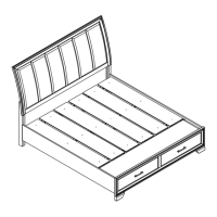
This document provides assembly instructions for the CROWN MARK (CRWN) furniture series, specifically for models B6580-Q-HB, B6580-K-HB, B6580-K-FBD, and B6580-KQ-RAIL. These models appear to be components of a bed frame, including a headboard, footboard, and side rails.

Function Description:

The primary function of these products is to form a complete bed frame. The headboard (A) serves as the decorative and structural backrest for the bed. The footboard (B) provides structural support at the foot of the bed and often includes storage features. The side rails (H) connect the headboard and footboard, defining the length of the bed and supporting the mattress foundation. The design incorporates various wooden components, including wooden panels (E), wooden slats (F), and slats supports (G), which together form the bed base. The footboard, in particular, seems to feature integrated storage compartments, enhancing its utility beyond mere structural support.

Important Technical Specifications:

The assembly relies on a variety of fasteners and components, indicating a robust construction.

  • Headboard Components:
    • Head Board (A): 1 unit.
    • HB Leg Post (L/R) (B): 2 units.
    • JCBC (M8) with Washer (C): 8 x P1.0 x 35MM, 4 units.
    • Allen Key M5 (D): 5 x 120MM, 1 unit.
  • Footboard Components:
    • Foot Board (B): 1 unit.
    • FB Leg (C): 2 units.
    • Leg Support for FB (D): 2 units.
    • Wooden Panel (E): 6 units.
    • Wooden Slat (F): 3 units.
    • Slats Support (G): 6 units.
  • Side Rail Components:
    • Side Rail (L&R) (H): 2 units.
  • Hardware for Footboard and Side Rails:
    • C.S.K Screw (M4) (I): 4 X 32MM, 6 units.
    • C.S.K Screw (M3.5) (J): 3.5 x 20MM, 18 units.
    • JCBC (M6) with Washer (K): 6 x P1.0 x 100MM, 2 units.
    • Allen Key M4 (L): 4 x 65MM, 1 unit.
    • A screwdriver is required but not included.

The use of M8 and M6 JCBC (Joint Connector Bolt Cap) screws with washers suggests a strong, secure connection for the main structural components. The CSK (Countersunk) screws are used for attaching wooden panels and slats, ensuring a flush finish. The inclusion of Allen keys for both M5 and M4 fasteners indicates that these are the primary tools for assembly.

Usage Features:

The assembly process is broken down into four distinct steps, designed for clarity and ease of construction.

  • Step 1 (Headboard Assembly): Focuses on attaching the leg posts (B) to the headboard (A) using JCBC (M8) screws with washers (C&D). The diagram shows a "BACK VIEW" and "FRONT VIEW" of the headboard, indicating careful attention to orientation during assembly.
  • Step 2 (Footboard Assembly): Involves attaching the FB leg (C) to the footboard (B) using JCBC (M6) with washer (K), and then affixing the leg supports (D) to the footboard. An important note here is to "Loosen or tighten Leg Support (D) as necessary to level the bed," highlighting a crucial adjustment for stability and proper alignment.
  • Step 3 (Side Rail and Bed Base Assembly): This is the most complex step, involving multiple sub-steps.
    • The side rails (H) are connected to the headboard and footboard. The diagram shows a "Press laterally into the groove and drop down" action, suggesting a specific interlocking mechanism for the side rails.
    • An "Important !!" note emphasizes the need to "LEVEL THE SIDE RAIL BY COVERING WITH A SOFT CLOTH AND TAPPING WITH A HAMMER," indicating that minor adjustments may be necessary to achieve proper alignment and stability.
    • The bottom rail supports (G) are affixed to the wooden slats (F).
  • Step 4 (Final Bed Base Assembly): The wooden slats (F) are affixed to the wooden panels (E) using CSK screws (J). The side rails (H) are then affixed to the wooden slats (F) using CSK screws (I). This step completes the bed base structure, ready to support a mattress.

The design appears to be modular, allowing for individual components to be assembled before being integrated into the final structure. The inclusion of leg supports for the footboard and multiple slats and supports for the bed base suggests a design focused on stability and durability. The footboard's design, with what appears to be integrated storage, adds a functional benefit for users.

Maintenance Features:

The manual includes critical maintenance instructions to ensure the longevity and safety of the furniture:

  • Periodic Tightening: "NOTE: MUST TIGHTEN SCREW PERIODICALLY. WITH USE SCREWS WILL BECOME LOOSE CHECK TIGHT OF ALL SCREWS EVERY 6-8 WEEKS." This is a standard but vital instruction for flat-pack furniture, addressing the natural loosening of fasteners over time due to movement and use. Regular checks and tightening prevent structural instability and potential damage.
  • Cleaning Instruction: "After assembled, clean & polish the complete parts if necessary with soft cloth and industrial recognized furniture polish." This suggests that the furniture may benefit from a final cleaning and polishing after assembly to enhance its appearance and protect the finish. The recommendation for "industrial recognized furniture polish" implies a durable finish that can withstand standard furniture care products.

Overall, the product is a comprehensive bed frame system designed for home assembly, with clear instructions and attention to structural integrity, functional features (like footboard storage), and long-term maintenance. The detailed parts list and step-by-step diagrams aim to make the assembly process manageable for the end-user.

Crown Mark B6580-Q-HB Specifications

General IconGeneral
BrandCrown Mark
ModelB6580-Q-HB
CategoryIndoor Furnishing
LanguageEnglish