English
5
English
6
d) Use special care when working corners, sharp edges etc. Avoid bouncing
and snagging the accessory .Corners, sharp edges or bouncing have a tendency
to snag the rotating accessory and cause loss of control or kickback.
e) Do not attach a saw chain woodcarving blade or toothed saw blade. Such
blades create frequent kickback and loss of control.
Additional safety instructions for grinding and cutting-off operations
Additional safety instructions for cutting-off operations
Safety Warnings Specific for Grinding and Abrasive Cutting-Off Operations:
a) Use only wheel types that are recommended for your power tool and the
specific guard designed for the selected wheel. Wheels for which the power tool
was not designed cannot be adequately guarded and are unsafe.
b) The guard must be securely attached to the power tool and positioned for
maximum safety , so the least amount of wheel is exposed towards the
operator. The guard helps to protect operator from broken wheel fragments and
accidental contact with wheel.
c) Wheels must be used only for recommended applications. For example: do
not grind with the side of cut-off wheel . Abrasive cut-off wheels are intended for
peripheral grinding, side forces applied to these wheels may cause them to shatter .
d) Always use undamaged wheel flanges that are of correct size and shape for
your select
ed wheel. Proper wheel flanges support the wheel thus reducing the
possibility of wheel breakage. Flanges for cut-off wheels may be different from
grinding wheel flanges.
e) Do not use worn down wheels from larger power tools . Wheel intended for
larger power tool is not suitable for the higher speed of a smaller tool and may burst .
Additional Safety Warnings Specific for Abrasive Cutting-off Operations:
a) Do not “jam” the cut-off wheel or apply excessive pressure .Do not attempt
to make an excessive depth of cut. Overstressing the wheel increases the loading
and susceptibility to twisting or binding of the wheel in the cut and the possibility of
kickback or wheel breakage.
b) Do not position your body in lime with and behind the rotating wheel. When
the wheel, at the point of operation, is moving away from your body , the possible
kickback may propel the spinning wheel and the power
tool directly at you .
c) When wheel is binding or when interrupting a cut for any reason, switch off
the power tool and hold the power tool motionless until the wheel comes to a
complete stop. Never attempt to remove the cut-off wheel from the cut while
the wheel is in motion otherwise kickback may occur. Investigate and take
corrective action to eliminate the cause of wheel binding.
d) Do not restart the cutting operation in the workpiece . Let the wheel reach
full speed and carefully the cut. The wheel may bind, walk up or kickback if the
power tool is restarted in the workpiece.
e) Support panels or any oversized workpiece to minimize the of wheel
pinching and kickback. Large workpieces tend to sag under their own weight.
Supports must be placed under
the workpiece near the line of cut and near the edge
of the workpiece on both sides of the wheel.
f) Use extra caution when making a “pocket cut ” into existing walls or other
blind areas . The protruding wheel may cut gas or water pipes, electrical wiring or
objects that can cause kickback.
Introduction
This tool is intended for grinding, cutting and deburring metal materials without the
use of water.
Do not apply pressure on the tool; let the speed of the cutting disc do the work
Cutting operations with bonded abrasive cut-off wheels are only allowed when a
cut-off guard is used.
Read and save this instruction manual.
1.Operating Controls
1.Auxiliary handle 2.Spindle lock button 3.Ventilation slots
4.Trigger of on/off switch 5.Threads(for auxiliary
handle)X3
6.Button of on/off switch
6*Rotating button 7.Grinding guard 8.Cutting guard
9.Inner flange 10.Grinding disc 11.Cutting disc
12.Outer flange 13.Spanner 14.Hex .screw
15.Hex. spanner
2.Assembly
Warning: Switch off the grinder and disconnect it from the power point.
Note: You must use the cutting guard when using the cutting disc .
1)The auxiliary handle (1) can be fitted to the left or the right or the above. Select the
position which gives the most comfortable and safe use.
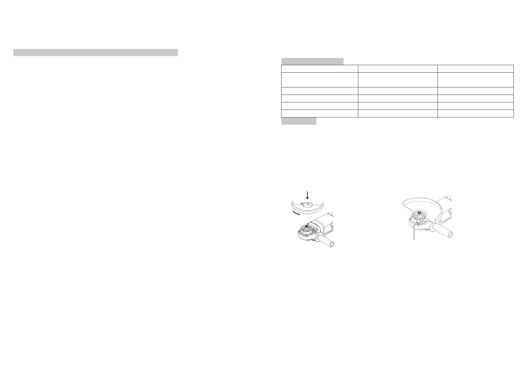
2)Fitting the grinding guard or cutting guard: (See figure 1 and 2)
A: Position the lug on the inside of the central guard ring in the vertical slot in he
spindle cover then twist the grinding or cutting guard to the appropriate position for
either grinding or cutting;
B: Tighten the hex .screw in a clockwise direction using the hex. spanner (15).
Figure 1
Figure 2
3)Fitting the grinding disc or cutting disc: (Figure 3 and Figure 4)
A.Place the inner flange (9) over the spindle making sure the fit is tight;
CAUTION: An O-ring is inserted in the inner flange around the spigot. If the O-ring is
missing or is damaged , it must in all cases be replaced before the inner flange is
mounted.
B.Place the grinding(10) or cutting disc (11 )on the top of the inner flange ensuring
the bore fits into the step of the flange;
C.Mount the concave recess side of the outer flange (12) over the spindle;
D.Press the spindle locking button (2) firm and ensure there is no movement in the
spindle. Then while the spindle lock is depressed tighten the outer flange in a
clockwise direction using the spanner (13).(See figure 5)
 Loading...