Operation Manual
I-Tech HD Series Power Ampliers
page 18
I-Tech HD Series Power Ampliers
Operation Manual
page 19
Pink Noise Generator: Press an Encoder knob to turn on the generator. Its
level will read –100 dB. Adjust the noise level from –100 dB to +20 dB in 0.5 dB
steps by turning Encoder 1 or 2. To turn off the generator, press an Encoder knob
or go to another menu item.
Input Sources: For each channel, turn the Encoder to select ana log, digital,
or automatic backup source. Options are:
Analog
Digital
Digital with analog backup <Digital A-Backup>
Digital with analog override <Digital A-Ovride>
Digital with analog backup: The I-Tech HD is being fed a digital signal and an
analog signal. The input is currently switched to the digital signal. If it fails, the
I-Tech HD switches instantly to the analog signal.
Digital with analog override: The input is switched to the digital sig nal, and no
analog signal is applied. If an analog signal is sent, the I-Tech HD switches
instantly to the analog signal. If the analog signal fails, the I-Tech HD switches
to the digital signal after a delay set by the Hold Time slider in the Input Section
of the System Architect page.
Maximum Analog Input: Turn an Encoder to select the maximum input level
to the amplifier: +21 dBu or +15 dBu. Press the knob to confirm your selection.
Note: Changing this value changes the range of sensitivities available to the
amplifier.
For more information see Figure 4.4 and the I-Tech Sensitivity Charts in the
Appendix of the I-Tech Application Guide. It is available online at www.
crownaudio.com/itech/pdf/137327.pdf.
Exit: To exit the Advanced Menu and go to the Attenuation screen, press Menu/
Exit once.
LevelMax - RMS Voltage Limiter: Limits the output rms voltage to an
amount that you set, either OFF or 1 to 500 volts, for each channel. Press the
Encoder to turn on the Limiter. Once it’s on, turn the Encoder to set the voltage.
Additional controls, such as attack, and release, are available through Sys tem
Architect.
4 Advanced Operation
Input Delay: Sets the input signal delay in each channel. Turn each channel’s
Encoder knob to vary the delay. The delay step size is speed sensitive. Pressing
the encoder enables or disables the Delay.
Below each channel’s delay setting is the equivalent distance in feet and meters.
For example, 10 ms is the signal delay of sound traveling 11.3 feet or 3.4 m.
Output Polarity: Press each channel’s Encoder knob to toggle the output
signal polarity between + and –.
Bandpass Gain: In each channel of the I-Tech HD’s DSP, just before the
output limiter and after the preceding filter, is a gain block (not shown on the
Signal Path block diagram). Bandpass Gain adjusts the gain of this block
between -24 dB and +24 dB.
Adjusting the bandpass gain in the LCD screen makes it easy to vary the level of
subwoofers, midrange drivers and high-frequency driv ers.
Front Panel Blackout: This screen lets you black out the front panel display
unless you press a front-panel button or turn an Encoder. This feature turns
off the LCD backlight and all front panel LEDs except for the fault LEDs and
power-switch green LED. After blackout is enabled, an Encoder press/turn
will “reactivate” the display. If no button is pressed/turned for 5 seconds, the
display will return to blackout mode.
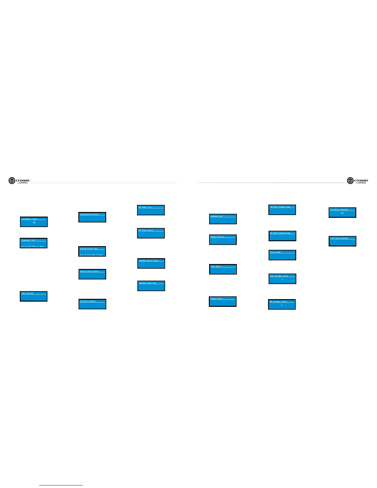
Attenuator Limits: You can set the maximum attenuation from 0 dB to
–100 dB. This feature allows you to set a limit on the attenua tors. Once set,
attenuation cannot be adjusted beyond this level. The attenuator limit appears
as a line in the attenuator bar meter.
NOTE: The attenuator setting must be below the attenuator limit that you are
trying to set. For example, if the attenuator is set at –3 dB, you cannot set the
attenuator limit below –3 dB unless you decrease the attenuator level.
0.0
Attenuator Limits
dB
0.0
Attenuator Link You can set the attenudators to be independent or linked.
Turn an Encoder knob to choose one of those options, then press the knob to
save your choice.
INDEPENDENT
Attenuator Link
Turn to Set-Press to Save
<Analog> <Digital>
Input Sources
Analog Source Select: Turn the left Encoder knob to select Analog 1,
Analog 2, or Analog 1+2 signals for Channel 1. The right Encoder does the
same for Channel 2. Press the knob to confirm your selection.
Analog 1 is Analog input Channel 1.
Anolog 2 is Analog input Channel 2.
Analog 1 +2 is Analog input Channels 1 and 2.
Analog Analog
Analog Source Select
1 2
+15dBu
Maximum Analog Input
Turn to Set-Press to Save
Digital Source Select: Turn the left Encoder knob to select the digital source
for Channel 1: AES or Cobranet. The right Encoder does the same for Channel
2. Press the knob to confirm your choice.
Digital Source Select
AES
<Cobra
net>
AES Source Select: Turn the left Encoder knob to select the digital source for
Channel 1: AES1, AES2, or AES1+2. The right Encoder does the same for
Channel 2. Press the knob to confirm your choice.
AES 1 is AES input Channel 1.
AES 2 is AES input Channel 2.
AES 1 +2 is AES input Channels 1 and 2.
AES
AES Source Select
AES
1
2
AES Input Trim: Turn the left Encoder knob to vary the gain of the AES digital
signal for Channel 1: -100.0 dB to +20 dB. The right Encoder does the same for
Channel 2. See Figure 4.4 for more information.
0.0
AES Input Trim
0.0
dB
AES Input Status: “Lock” indicates that an AES cable is plugged in and the
amplifier is receiving (and locking to) the AES clock pulse. “No Lock” means
that the amplifier is not receiving, or is not locking to the AES clock pulse.
No Lock
AES Input Status
CobraNet Source Select: Turn the left Encoder knob to select the CobraNet
source for Channel 1: Cnet1, Cnet2, or Cnet 1+2. The right Encoder does the
same for Channel 2. Press the knob to confirm your choice.
Cnet1 is Bundle A.
Cnet2 is Bundle B.
Cnet 1+2 is Bundles A+B.
Cnet 1
Cobranet Source Select
Cnet 2
CobraNet Input Trim: Turn the left Encoder knob to vary the gain of the
CobraNet digital signal for Channel 1: -100.0 dB to +20 dB. The right Encoder
does the same for Channel 2. See Figure 4.4 for more information.
0.0
Cobranet Input Trim
0.0
dB
0.0
Bandpass Gain
0.0
dB
+
Output Polarity
+
Press enc to toggle
0.0000
Input Delay
0.0/0.0
0.0000
0.0/0.0
ms
ft/m
Output Delay: Sets the output signal delay in each channel. Turn each
channel’s Encoder knob to vary the delay. The delay step size is speed sensitive.
Pressing the encoder enables or disables the Delay.
Below each channel’s delay setting is the equivalent distance in feet and meters.
For example, 10 ms is the signal delay of sound traveling 11.3 feet or 3.4 m.
0.0000
Speaker Delay
0.0/0.0
0.0000
0.0/0.0
ms
ft/m
LED Meter Display Type : Here you can set the LCD bar meters to display
average or peak levels. Turn an Encoder knob to select the option, then press
the knob to confirm your selection.
Bar Meter Display Type: You can select what the bar meters will display in
the Attenuator Screen. Press an Encoder knob to select Attenuation, Input
Levels, Output Levels, or Thermal %. Attenuation is displayed as the length of
the bar meters in the Atten uation screen that appears on startup. The meters
display average input levels and output levels.
ATTENUTATION
Bar Meter Display Type
Turn to Set-Press to Save
LevelMax- Peak Voltage Limiter: Limits the peak output voltage to a level
that you set, either OFF or 1 to 500 volts, for each channel. Press an Encoder to
turn on the Limiter. Once it’s on, turn the Encoder to set the voltage. Additional
controls, such as attack and release, are available through System Architect.
LevelMax - Clip Limiter: Limits the peak output voltage to just below
clipping for each channel. Press an Encoder knob to turn it OFF or ON.
OFF
Clip Limiter
OFF
OFF
Peak Voltage Limiter
OFF
v
OFF
RMS Voltage Limiter
OFF
v
OFF
Pink Noise Generator
OFF
dB
4 Advanced Operation
OFF
Front Panel Blackout
AVERAGE
LED Meter Display Type
Turn to Set-Press to Save
 Loading...