This document outlines the installation and operation of the CRUISE CONTROL AP900Ci/GC90Ci system, a device designed to provide cruise control functionality in vehicles. The manual covers CAN-Bus connection, software unlock procedures, pedal learning mode, diagnostic mode, initial adjustment, gain adjustment, CAN search, analog mode activation, analog connections, learning of speed signal, and error codes.
Function Description
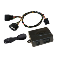
The CRUISE CONTROL AP900Ci/GC90Ci system is a vehicle accessory that enables cruise control functionality. It allows the driver to maintain a set speed without continuously pressing the accelerator pedal. The system integrates with the vehicle's engine control unit (ECU) and accelerator pedal, either via the CAN-Bus network or through analog connections. It features a control module (CM) for user interaction, a T-harness for connecting to the accelerator pedal, and a diagnostic socket for system monitoring. The device can operate in two primary modes: CAN-Bus mode for modern vehicles with a CAN network, and Analog mode for vehicles where CAN signals are not available or compatible.
In CAN-Bus mode, the system communicates digitally with the vehicle's ECU, leveraging existing vehicle data for speed control. This mode is generally preferred for its seamless integration and reduced wiring complexity. The installation involves connecting the system to the vehicle's CAN High (pos. 6) and CAN Low (pos. 14) wires, typically found at the OBD connector. The manual explicitly states that the OBD adapter supplied with the GC90Ci kit must not be used, and wires must be soldered behind the OBD connector for a secure and reliable connection.
In Analog mode, the system relies on direct electrical signals from various vehicle components. This mode is activated if CAN signals are not available or if the CAN search procedure fails. In this mode, additional analog wires must be connected: ORANGE for ignition (+12V), BLUE for vehicle speed pulse (ground pulses), BROWN for the hot side of the brake switch (+12V), BROWN/WHITE for the cold side of the brake switch (+12V when the brake pedal is pressed), and VIOLET for the clutch switch wire (ground state changes when the pedal is pressed). The analog connections are typically made to the accelerator pedal's high signal, low signal, and ground, as well as to the ignition, brake pedal, clutch pedal, and speed pulse. A resistor may be recommended for boosting the speed signal, connected between the Orange and Blue wires.
The system includes several operational features:
- Speed Limiter: The CM allows the driver to switch the speed limiter ON or OFF.
- Set Speed: The SET key on the CM is used to set and adjust the desired cruise control speed.
- Resume Speed (RES): The RES key on the CM is used to resume a previously set speed.
- Buzzer Feedback: The system provides audible feedback through a buzzer for various operations, such as software unlock, pedal learning, and diagnostic checks. Different beep patterns (e.g., 1 low 2 high tones, 4 low tones, 3 long beeps, 4x high + low tones, 4x high tones) indicate the status or success of a procedure.
- LED Indicator: A LED on the central unit provides visual feedback, particularly during CAN search and diagnostic modes.
Important Technical Specifications
While specific numerical technical specifications (e.g., voltage, current ratings) are not explicitly detailed in the provided pages, the manual implies several technical aspects:
- CAN-Bus Compatibility: The system is designed for vehicles with a CAN-Bus network, specifically utilizing CAN High (pos. 6) and CAN Low (pos. 14) lines.
- Analog Signal Compatibility: It supports various analog input signals, including +12V ignition, ground pulses for vehicle speed, +12V for brake switch (hot and cold sides), and ground state changes for clutch switch.
- Accelerator Pedal Integration: The system connects to the accelerator pedal's high signal, low signal, and ground wires. The manual notes typical voltage ranges for these signals (e.g., High signal: 1.4V - 4.0V or 1.3V - 4.2V; Low signal: 0.7V - 2.0V or 0.6V - 3.5V).
- Error Code Generation: The system is equipped with an error code generator that indicates abnormal conditions through a series of beeps, helping diagnose issues.
Usage Features
The CRUISE CONTROL AP900Ci/GC90Ci system offers several usage features that enhance the driving experience:
- Software Unlock: This is a mandatory initial step after installation, ensuring the software is properly activated. It involves a sequence of CM operations (switching ignition ON, switching speed limiter ON, pressing and holding SET, pressing and releasing the brake pedal 4 times) with specific buzzer feedback.
- Pedal Learning Mode: This mandatory procedure calibrates the system to the vehicle's accelerator pedal. It involves a sequence of CM operations and pedal presses (e.g., pressing and holding the BRAKE pedal, pressing the SET key multiple times, gently pressing the accelerator to full throttle) to learn the pedal's full range.
- Diagnostic Mode: An optional mode that allows the user to check the functionality of the CM, brake signal, clutch signal, accelerator pedal control, and vehicle speed signal. This helps in troubleshooting installation issues.
- INIT Adjustment (Optional): This feature allows adjustment of how aggressively or slowly the limit speed is reached. A higher "init" setting means the system will initially go over the limit speed and then slow down, while a lower setting means it will slow down a bit and then stabilize. This is adjusted through a sequence of CM operations and driving at a certain speed, with buzzer feedback indicating the activated init level.
- GAIN Adjustment (Optional): This feature adjusts how the limiter reacts when driving at the limit speed. A high "gain" setting results in steady speed but a constant throttle feel, while a low setting causes continuous movement around the limit speed. Similar to INIT adjustment, this is configured through CM operations and driving, with buzzer feedback for the activated gain level.
- CAN Search: An optional procedure to find suitable CAN software if the initial "Software unlock" fails. The system searches for compatible CAN signals and, if found, automatically switches to CAN mode without requiring further "Software unlock."
- Learning of Speed Signal: This procedure, performed in analog mode, calibrates the system to the vehicle's speed signal. It involves driving at a specific speed (e.g., 72 km/h) and performing CM operations to allow the system to learn the speed signal. This procedure can also be used to calibrate the speed signal in CAN mode.
Maintenance Features
The manual provides guidance for troubleshooting and ensuring proper operation, which can be considered maintenance-related features:
- Error Codes: The system generates error codes indicated by beeps, which help diagnose specific issues. For example:
- 1 beep: control function pressed for more than 20 seconds.
- 2 beeps: acceleration speed more than 9 kph per second.
- 3 beeps: speed drops below 33 km/h.
- 4 beeps: speed exceeds 250 km/h.
- 5 beeps: speed drops below 75% of the current set speed.
- 6 beeps: speed exceeds 150% of the current set speed.
- 7 beeps: throttle pedal not calibrated.
- 8 beeps: speed increases abnormally.
These error codes are crucial for identifying and resolving operational problems.
- Troubleshooting during Installation: The manual provides specific instructions for troubleshooting during the software unlock and pedal learning phases. For instance, if the software unlock test is not passed, it suggests checking if the right vehicle is selected for programming and repeating the test, or even starting the engine on step 1. If pedal learning does not go through or tones do not match, the user is advised to restart programming from the beginning.
- Diagnostic Checks: The diagnostic mode allows for checking the functionality of various components and signals, aiding in identifying wiring issues or faulty components. For example, if there's no beep signal during CM operation, it suggests checking the CM and its wiring. If there's no beep signal for the brake pedal, it advises checking CAN wires or analog brake wires.
- Analog Mode Activation: If CAN signals are not available or the CAN search fails, the system can be switched to analog mode, providing an alternative operational path and ensuring the cruise control functionality can still be utilized. If CAN signals are later found, the system can be switched back to CAN mode via the CAN search procedure.
The manual emphasizes the importance of referring to model-specific installation manuals from Beijer Automotive for detailed connection points, especially for CAN-Bus wires. It also provides contact information for ProTeam OÜ for support.