Emissions Tester CCP700/800 Series Hints & Tips
16
Bluetooth Smoke Head charging contacts
Bluetooth Smoke Head equipment can experience charging issues due to faulty or corroded
charging contacts. This problem can be caused by several factors which need to be looked at
individually, but there are three main areas of corrective procedure:
• Charger base microswitch height adjustment
• Charger base contact replacement
• Smoke Head contact replacement
Ensure equipment is isolated from the mains supply before commencing work on the charger
assembly. Ensure the battery pack output terminals can NOT be ‘shorted’ together at anytime
during the Smoke Head contact replacement procedure.
Adjustment of the Microswitch
Charger base microswitch height adjustment should be set so that the microswitch is heard to
operate when the Smoke Head rubber foot is between 1-2mm from the charging base. If the
microswitch is set to operate at a too high a setting then arcing of the charging contacts will
occur. If it is set too low then it may fail to activate.
Charger base contacts
Replacement may be required if the contacts have become severely corroded. Corrosion will
occur if arcing has been taking place due to incorrect microswitch adjustment or can be a result of
the contacts becoming dirty from contaminants and debris picked up from the workshop floor.
Restricted movement of the contacts may also occur as a result of dirt or excessive heat from
arcing.
Smoke Head charger contacts
Replacement may be required if the contacts have become severely corroded
Good The contact has slight wear, but otherwise acceptable.
Poor The contact is slightly corroded through contact with
dirt etc. Also, small signs of pitting of the plating.
Bad The contact shown left is showing bad signs of arcing
and corrosion and should be replaced.
Emissions Tester CCP700/800 Series Hints & Tips
17
Battery Replacement
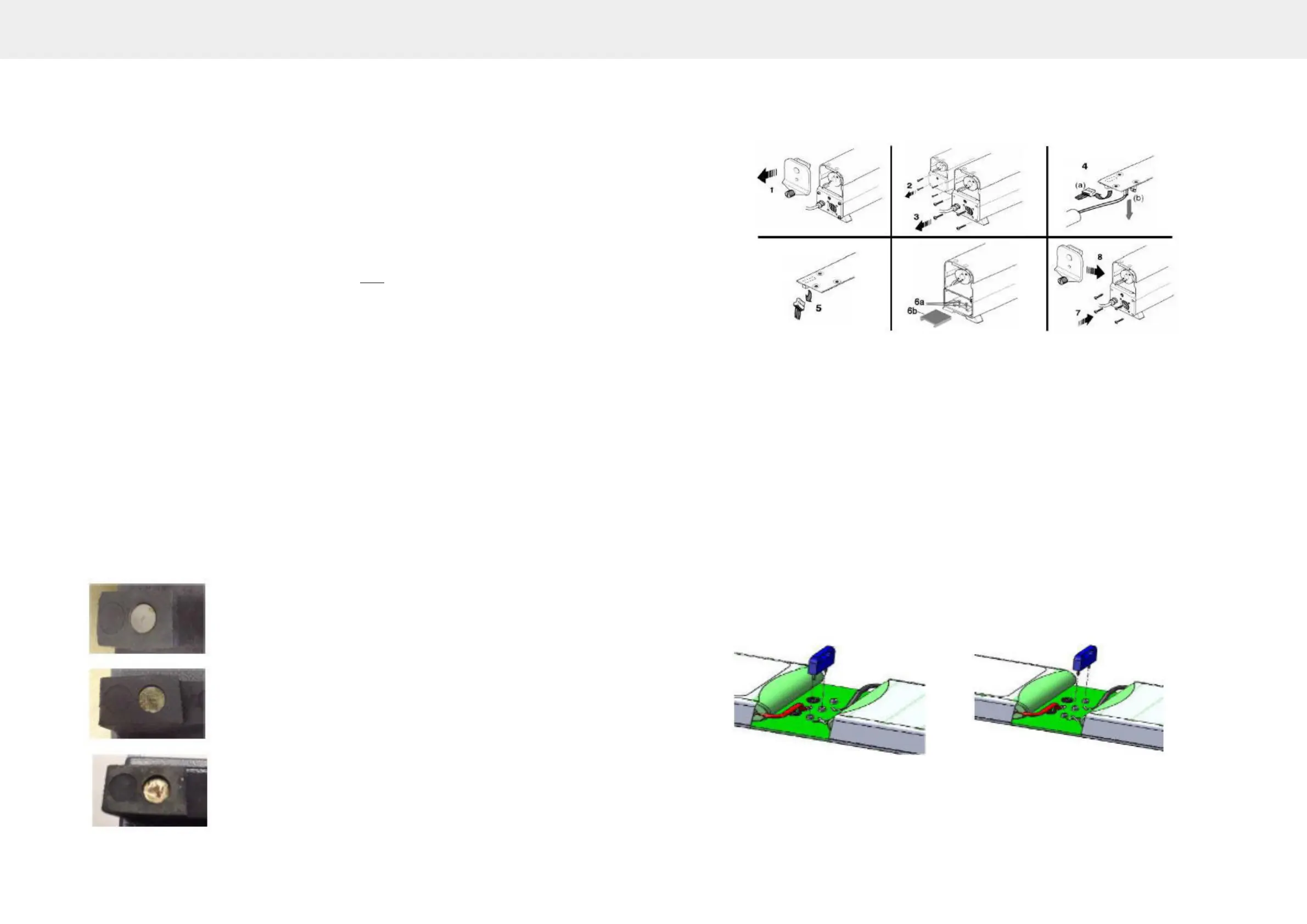
Removal:-
• Unscrew the knurled knob (1) and open up both end caps.
• Remove the four pan head screws (2) & (3) securing both end plates and carefully ease
the plates clear of the housing
• At the fan end, disconnect the 2-pin battery plug (4a) and the 2-pin fan plug (4b)
• At the probe end, disconnect the 3-pin plug (5)
• Depending on which version you have either - loosen the two screws (6a) or remove the
plastic spacer (6b) securing the battery pack
• Discard the two securing screws or the plastic spacer– they are no longer required
Note the orientation and remove the battery pack. Do not remove by pulling the cables, and
ensure the connectors do not foul any components during removal of the board.
Move the activation link from the transit position Fig. 1 to the live position Fig. 2.
Fig. 1 - Activation link - Transit position Fig. 2 – Activation link – Live position