Maintenance Guide CCP800 series
9
Maintenance Guide CCP800 series
8
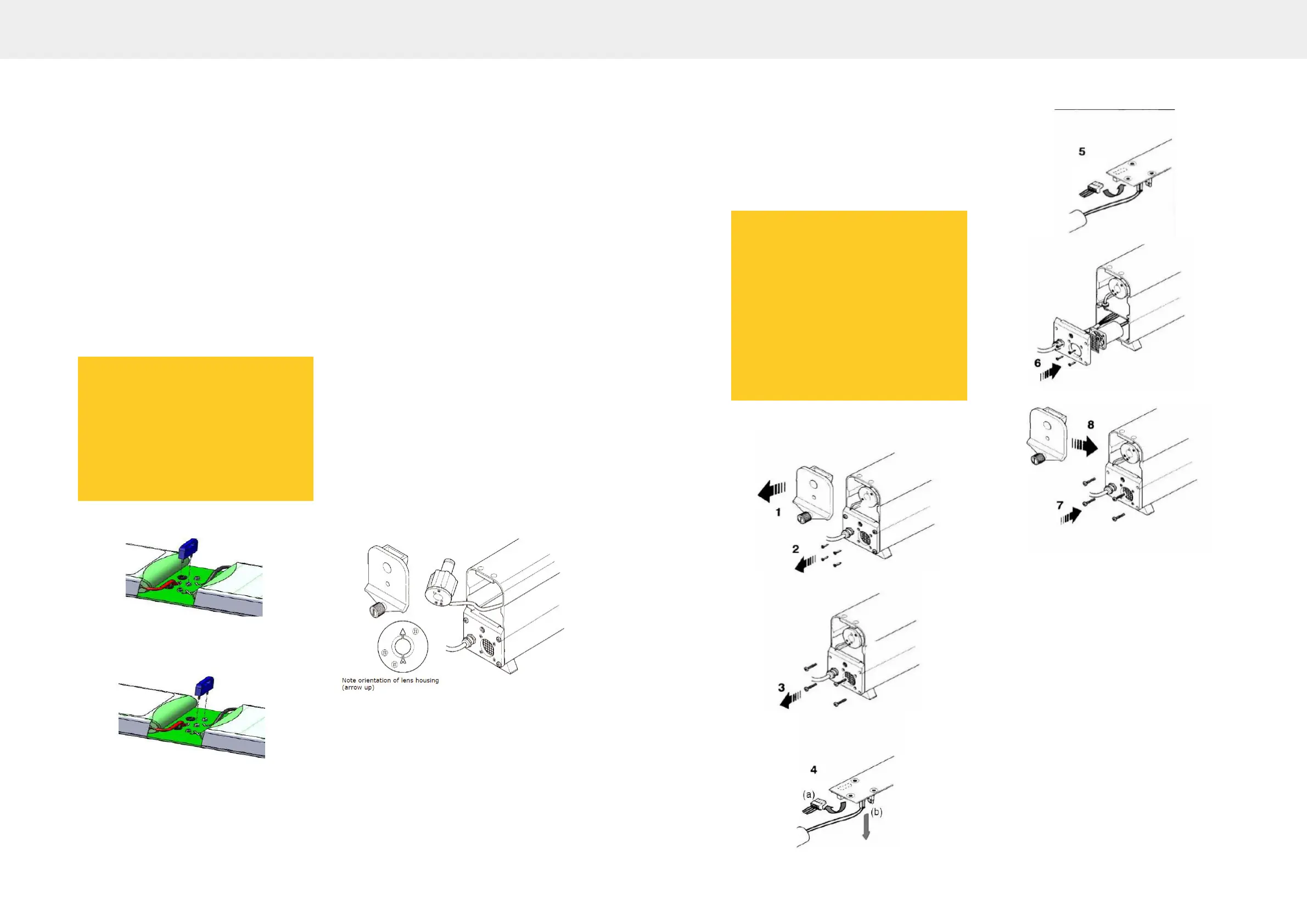
Removal:-
■ Unscrew the knurled knob (1) and open
up both end caps.
■ Remove the four pan head screws (2) &
(3) securing both end plates and carefully
ease the plates clear of the housing
■ At the fan end, disconnect the 2-pin
battery plug (4a) and the 2-pin fan plug
(4b)
■ At the probe end, disconnect the 3-pin
plug (5)
■ Depending on which version you have
either - loosen the two screws (6a) or
remove the plastic spacer (6b) securing
the battery pack
■ Discard the two securing screws or the
plastic spacer– they are no longer
required
Fig. 1 - Activation link - Transit position
Fig. 2 – Activation link – Live position
Replacement:
■ Your new battery pack is supplied with the
activation link in the ‘transit’ position
(marked ‘X’) see Fig. 1. This must be
moved to the ‘Live’ position (Marked ‘√’)
to activate the battery before it is installed
into your smoke head, see Fig. 2
■ Slide the new battery pack into position
(note orientation)
■ Re-connect the 2-pin plug (4a), the 2-pin
plug (4b), and the 3-pin plug (5)
■ Relocate the end plates to the smoke
head and loosely secure with 4 pan head
screws (7)
■ Check that the lens housings are fully
located, then t the end caps and secure
with the knurled knob. Fully tighten the
knurled knob then slacken half a turn (8)
■ Push the end plate upwards as far as it will
go, and then fully tighten the 4 pan head
screws.
■ Fully tighten the knurled knob on the end
caps
5.6 Lens Cleaning
Two lenses are tted in the smoke head, one
at either end. The smoke meter checks the
cleanliness of the lenses at the start of each
test, and the PC will provide a warning when
cleaning is required.
New orientation of lens housing (arrow up)
5.7 Accessing a lens
■ If tted, remove the sampling pipe
■ Unscrew the knurled knob at the sampling
pipe end of the sampling head and
remove the end cap.
■ Carefully pull out the lens housing and
wipe the lens with a soft cloth (if required,
a little methylated spirit will assist
cleaning)
Note:
The orientation and remove the battery
pack. Do not remove by pulling the
cables, and ensure the connectors do not
foul any components during removal of
the board.
Move the activation link from the transit
position Fig. 1 to the live position Fig. 2.
■ Ret the lens housing with the arrow
pointing upwards (a little silicon grease on
the 'O' ring will assist tment – but do not
get on lens!)
■ Ret the end cap and tighten the knurled
knob
5.8 Cable & Fan Removal
Should the cable become damaged and
require renewal, the procedure is as
follows:
■ Unscrew the knurled knob (1) and remove
the end cap
■ Remove the four countersunk screws (2)
which secure the internal fan and grille to
the smoke head end plate
■ Remove the four pan head screws (3)
securing the end plate and carefully ease
the plate clear of the housing
■ Disconnect the 4-pin multi-plug (4a). If
carrying out a fan replacement disconnect
the 2-pin plug (4b) and replace the fan.
Carefully t the fan and fan grille to the
end plate (4 countersunk screws)
■ Remove the 4 wires from the 4-way plug.
Undo the metal cable clamp from the end
plate. Loosen the cable gland strain relief
and remove the cable from the end plate
■ Re-t the new cable through the cable
gland strain relief and secure to the end
plate with the metal clamp (Important:
secure the clamp on the earth braid of the
cable). Re-t the 4-way plug. Ensure the
NOTE:
Ensure the end cap locates fully against
the body of the sampling head before
tightening the knob. If not correctly
located, the lens housing is probably not
fully home.
1. Clean the lens at the other end of the
smoke head in the same way.
NOTE:
The end cap for the sampling pipe must
be tted at the end away from the
sampling head cable.

 Loading...