PART NO. MS0070
>
REvISION 3
>
JULY 2017 V2
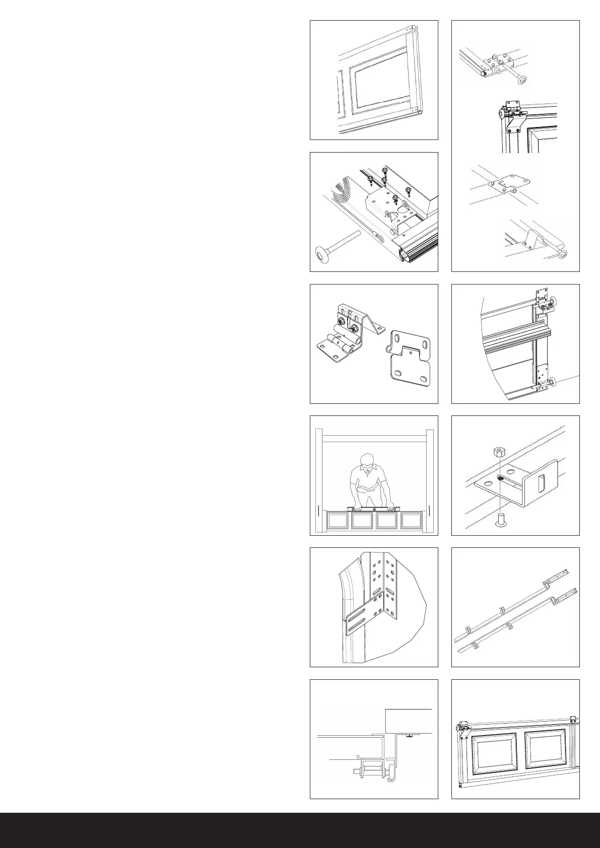
STEP 1
Select door panel with weather seal pre-installed to bottom edge. Place this
panel face down on a soft support (eg, two padded saw horses) (FIGURE 1).
STEP 1A/B
Select from FIGURE 1A the bottom cable bracket and fit to each bottom
corner of the panel using 5 x 1/4” metal screws. Attach one cable over steel
extrusion either end (FIGURE 1B).
STEP 1C
Using the 2 x end hinge (FIGURE 1C) attach 1 hinge to each end stile of the
panel and fit the centre hinges to all intermediate stiles. Ensure hinge pivot
point is level with top edge of the panel. Fit 4 wheels and axles to each outer
hinge (FIGURE 1D).
LUBRICATION: Ensure that all roller shafts are dipped in grease
before installation. Lubricate all hinges in holes provided.
STEP 2
Stand door panel upright and central to garage door opening and ensure it is
level by placing spirit level on top edge of door panel (FIGURE 2). If panel is
not horizontally level it is important to use suitable packer underneath
door panel to achieve level. Ensure there is an even overlap on either side.
Mark a point 10mm past either end. Using a straight edge pencil mark a vertical
line on both sides of the opening (place a temporary prop against the panel).
STEP 3
Cut the vertical tracks from the bottom as a pair. They are cut door height
minus 280mm for std head single track and 405mm for low head
double track. Loosely fasten the wall fix brackets to each vertical track
using the 1/4” x 5/8” screws and nuts as shown. The screw heads must be
inside the track (FIGURE 3A). The smaller wall bracket is fixed to the bottom
of the track, with the larger bracket above.
IMPORTANT: Ensure the flat edge of the track is facing the wall.
Attach the flag brackets to the top of the track with the 1/4” x 5/8” screws
and nuts, once again screw heads must be inside the track (FIGURE 3B & C).
STEP 4
Install each vertical track by passing it over the bottom panel wheels already
in the opening. Using suitable fixings align inside edge of each track with
pencilled line as detailed in STEP 2 and FIGURE 4 and make sure tops of
tracks are level with each other.
STEP 5
Attach end hinges first to each end of the next door panel then attach
the centre hinges to each vertical rigid section between the two outer end
hinges by working your way towards the centre (FIGURE 6). Place a piece
of cardboard on top of the bottom panel where it mates with the
next panel to maintain the required gap between panels. Lower this
panel on top of the bottom panel (FIGURE 7).
STEP 6
Repeat STEP 5 to the third panel. NOTE: If your CSI
®
Classic has more
than 4 door panels it will be necessary to repeat the process again
using end hinges and centre hinges before proceeding.
STEP 7
Place the last section (top panel) face down, attach the top corner brackets
to the door panel as shown in FIGURE 8. The top brackets are secured
using four tek screws. Do not install final panel until STEP 12.
STEP 8
Adjust wheel and axle carriers so that the panels are in a vertical alignment
without scraping the wall or binding in the tracks.
IMPORTANT: Do not force the track too tightly against the rollers as
this will cause the door to bind when in operation.
Check that all door panels are level, make necessary adjustment if required
Once satisfied secure all wall mounted brackets to eliminate any further
track movement (FIGURE 9).
HORIZONTAL TRACKS
STEP 9
Use a suitable support to hold the back of the horizontal track in position
(FIGURE 10). NOTE: the 22” reinforcement angle always goes on the
lower track in Low headroom installations.
STEP 10
Attach the curved section of the horizontal track to the flag bracket using the
1/4” x 5/8” screws and nuts. Ensure that the screws are on the inside of the
track. Attach the end of the horizontal angle to the top of the wall mounted
flag bracket, the 3/8” x 3/4” carriage bolt and nut (FIGURE 11). Make sure
the horizontal and vertical tracks are aligned when joined.
Door
Wall
Side
Top
View
Centre
Hinge
End
Hinge
FIGURE 4 FIGURE 6
FIGURE 1A
End
Hinge
Bottom
Cable
Bracket
Top
Corner
Bracket
FIGURE 2
FIGURE 3B FIGURE 3C
Bottom
Top
FIGURE 3A
FIGURE 1C
FIGURE 1B
FIGURE 1
Bottom
Top
End Hinge
Centre Hinge
FIGURE 1D
Centre
Hinge
 Loading...