PART NO. MS0070
>
REvISION 3
>
JULY 2017 V2
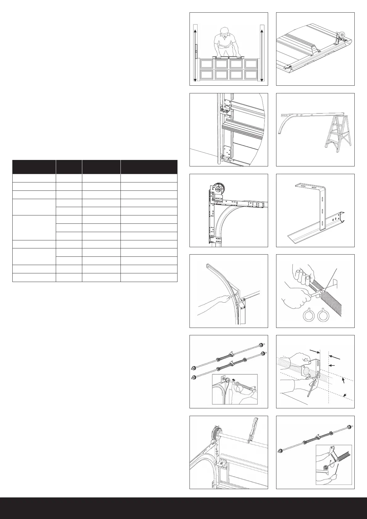
STE P 11
Secure the rear of the horizontal track with steel angle brackets supplied, if
not suitable it will be necessary to fabricate from other material. Make sure
that the track is level and square with the opening. Due to the fact that the
horizontal tracks are weight bearing, when the door is fully opened ensure
that adequate fasteners are used into solid fixings (FIGURE 12). Repeat this
step for the second horizontal track.
STEP 12
Fit the top panel by removing the sliding section from each top hangar and
placing the panel in position with cardboard between the joint to the panel
below, refit the sliding section with the axle into the track fit bolts and nuts
do not tighten, fit fixings to the hinge below.
The sliding section on the top door panel bracket should be loose. Push
roller to the front of the front of the guide and adjust top panel leaving
enough clearance between head and jamb. Once satisfied that the roller is
correctly positioned in the track then tighten the slide bracket (FIGURE 13).
REINFORCING BRACING
STEP 13
These are placed as follows:
When fixing reinforcing ensure 2 fixing are placed at each end and to every
intermediate stile (FIGURE 8).
SPRING AND SHAFT ASSEMBLY
STEP 14
Attach the bearing plate to each horizontal angle on both tracks using
carriage bolts and nuts (FIGURE 11).
STEP 15
Secure the spring anchor plugs to the centre bearing. Locate the left wound
spring to the right side of the plate and the right wound spring to the left of
the plate. If your door only requires one wound spring locate it to the left or
right as detailed above. Slide the completed spring assembly over the shaft
and slide into place the cable drums at each end. Ensure that the correct
drums are on the right ends as marked (FIGURE 14 and 15 also ATTENTION
INSTALLERS diagram on following page).
STEP 16
Place the shaft assembly over the horizontal tracks and slide one end
through the bearing plate with the greatest side clearance, then insert the
opposite end into its bearing plate (FIGURE 15).
STEP 17
Take hold of the spring bearing plate and raise it until the shaft is level.
Position the bracket near the centre of the header so that the opener can be
fixed in the centre and securely fix to the wall (FIGURE 16).
STEP 18
Pull the cables up in the space between the tracks and the door. Align the
cable over the back of the cable drum and insert in the cable slot. Lay the
cable over the highest outside groove of the drum and tighten cable drum
onto the shaft place a clamp onto the shaft and against the lintel to prevent
the cable unwinding (FIGURE 17). Repeat for the second cable and drum
making sure both cables and drums are evenly aligned.
FIGURE 13
FIGURE 10
FIGURE 12
FIGURE 8
FIGURE 14 Two spring arrangement
Left
wound
spring
Right
wound
spring
Spring
Anchor
Plug
L.W.S R.W.S
FIGURE 15
FIGURE 17
FIGURE 16
FIGURE 18
Guide only
2100mm high
- approx 7.5 turns
2400mm high
- approx 8.5 turns
+/- 75mm
Door
centre
line
Centre line
between bearing
holes
Line B
FIGURE 9
FIGURE 7
DOOR WIDTH
PANEL
QTY
REO QTY FIT TO
0 - 3,570mm 4-6 0 n/a
3,575 - 4,600mm 4-6 1 top
4,605 - 4,900mm 4-6 2 top + bottom
4,905 - 5,250mm
4 2 top + bottom
5-6 3 top + bottom + middle
5,255 - 5,510mm
4 2 top + bottom
5 3 top + bottom + middle
6 5 miss the middle panel
5,515 - 5,930mm 4-5 3 top + bottom + middle
5,935 - 6,100mm
4 3 top + bottom + middle
5 4 miss the middle panel
5,515 - 6,100mm 6 6 all the panels
6,105 - 6,500mm 4-6 reo all panels
all the panels
FIGURE 11
 Loading...