Page 4-C
3.3. Each unit will vary based on model but can give off up to 63,000 BTU/Hr. (18.46 KW) of heat into the
room it is installed in. This heat must be removed to maintain the chamber environment specs.
3.4. The chamber must be installed in an environment between 65°F (18.3°C) and 85°F (29.4°C) with a
maximum humidity of 95% at a maximum elevation of 7,000 ft. (2133.6 m) for proper operation.
3.5. The unit can be leveled by adjusting the leveling feet using a 1/2” (13 mm) open end wrench.
4. Connect Necessary Utilities
4.1. Connect supply power to the chamber through the 1-1/4” EMT conduit to TB-1 on the electrical sub-
panel, reference data tag for proper power requirements. All electrical connections and adjustments
should be performed by a licensed electrician.
4.2. Connect humidity supply water using a 1/4” plastic water hose. (optional)
4.3. Route or connect 1/2" chamber drain to an open air drainage system.
4.4. Connect Refrigeration Water (If applicable)
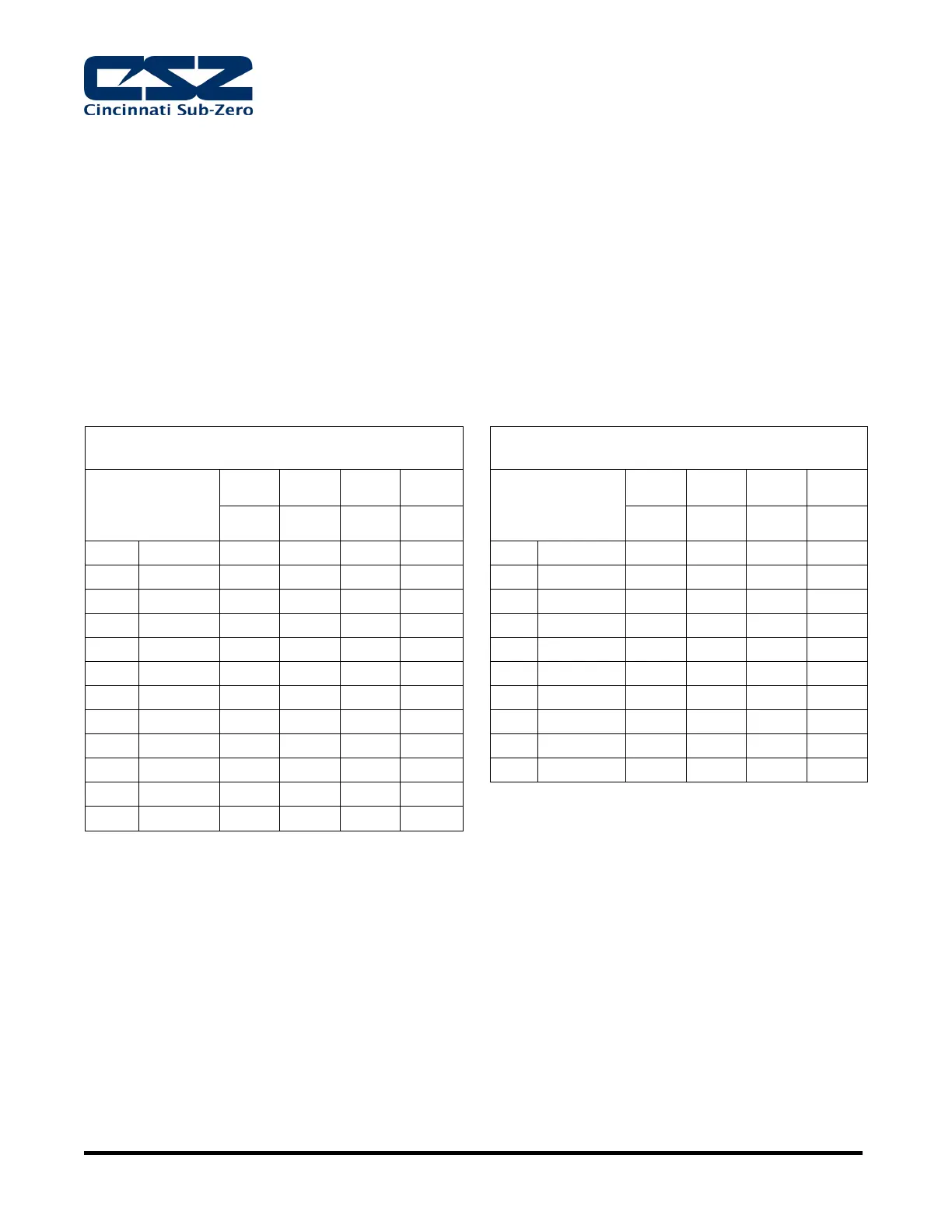
4.4.1. Review data tag for proper HP rating and find the proper connection size and flow rates below.
LOW TEMP HERMETIC & SEMI-HERMETIC
COMPRESSORS
LOW TEMP SCROLL COMPRESSORS
WATER
TEMPERATURE
85°F 75°F 65°F 55°F
WATER
TEMPERATURE
85°F 75°F 65°F 55°F
29°C 24°C 18°C 13°C
29°C 24°C 18°C 13°C
4.5. Connect 4” cuff pressure relief vent to ventilation system. (optional, but required on units with LN2 or
GN2 systems to eliminate the risk of asphyxiation)
4.6. Refer to user manual for communication connections and all other optional connections.
4.7. For ease of service it is recommended:
4.7.1. Utility connections should be flexible and at least 3’ (92 cm) in length.
4.7.2. Main power disconnect should be installed on incoming power.
 Loading...