Do you have a question about the CTC Union SC310 Series and is the answer not in the manual?
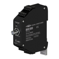
The SC310 Series Signal Conditioner is a DIN rail mountable device designed for continuous machinery monitoring applications. It converts a sensor input into a buffered dynamic output of the vibration waveform, as well as 0-20 mA, 4-20 mA, 0-5 Vdc, or 0-10 Vdc output signals. It also includes dedicated pins for input from a temperature sensor and a 4-20 mA signal proportional to the temperature sensor input voltage. The signal conditioner accepts input from an accelerometer, velocity transducer, or proximity probe, and its output can be configured proportional to acceleration, velocity, or displacement. All settings are configured using downloadable and easy-to-use software, which requires a PC and a micro USB cable.
The signal conditioner requires a +20 - 32 Vdc power lead connected to terminal 5 and the negative or common to terminal 6. For single channel accelerometer input, the sensor leads connect to terminals 13(+), 14(-), and 15 (shield drain wire). If using a TA series sensor, the temperature output lead attaches to terminal 16. The output device connects to terminals 11(+) and 12(-) for channel one's 4-20 mA signal proportional to the vibration level. Output device for temperature connects to terminals 1(+) and 2(-) to obtain the 4-20 mA signal representative of temperature level. Terminals 7(+) and 8(-) are inactive for single channel signal conditioner builds. The dynamic signal output can be obtained from the BNC connector at the top of the signal conditioner or from terminals 3(+) and 4(+).
For biaxial and triaxial accelerometers, the SC300 Series signal conditioners are compatible, but wiring differs. Each vibration input requires a unique signal conditioner. A triaxial sensor requires three SC300 units, and each biaxial sensor requires two SC300 units. Each axis of vibration has its own signal conductor wire, which runs to a separate SC300 or terminal 13. The black common conductor should be daisy chained to terminal 14 of the remaining signal conditioners.
The configuration software requires Windows 10 minimum build version: 1703 or .NET Framework 4.7.2. Approximately 1GB of free storage (5GB recommended) is needed to create application files, log files, and database records.
To install the software:
After installation, run the CTC Signal Conditioner Application. The first thing that appears is a device select screen. If multiple devices are plugged in, a pop-up window may display requesting that one be connected. It is crucial to plug multiple devices in at the same time due to USB serial driver limitations. If the device is unplugged, the devices should resolve the issue. If a signal conditioner is connected, it will appear automatically in the list.
The configuration software allows changing several controls for the selected device. The Part Number text box displays the part number, and the Serial Number box displays the serial number. The Device Type box shows whether the currently selected Signal Conditioner is Single Channel or Dual Channel.
Once all wires are connected and power is applied, the signal conditioner begins operating. The status light settles to normal mode. If the software reports an error, it means the error is currently present on the signal conditioner. The LED indicator provides visual status:
When collecting waveform data from the BNC jack on the signal conditioner using a portable data collector, it is recommended that the data collector is configured so that power to the sensor is turned off. Although the BNC connector circuitry offers short circuit protection and can safely sink current, long-term degradation may occur due to increased power dissipation depending on the magnitude of the IEPE current. There is no need for the data collector sensor power to be turned on for the data collection to be made, and it is the safest way to make measurements if possible.
If the SC300 is correctly connected via USB and the software is properly installed, the serial number of the device will appear in the dropdown menu. If a serial number doesn't appear, check the USB connection to make sure it is secure. Confirm that the LED indicator on the SC300 unit is lit up with a solid orange light (LED will blink when first plugged in and should then turn solid orange).
If both steps above are confirmed, but the device is still not recognized, there might be missing critical PC drivers. Navigate to the Device Manager (through the Start menu on Windows Devices) and look for the drop-down menu on the left side of the page. Look for and select the "Other Devices" option, then right-click on "USB Serial Port." Select the "Update Driver" option, then "Search Automatically for Drivers." If the driver updates correctly, there will no longer be a "USB Serial Port" option in the "Other Devices" section, and a new option will appear in the "Ports" section of the drop-down tree, showing "Communications Port (COMX)" and "USB Serial Port (COMX)."
If a notification appears that there is no available upgrade, the driver will have to be installed manually. The link for the driver is: https://ftdichip.com/drivers/vcp-drivers/. Scroll down to the download link section and select the setup executable option on the left side. Save the file and run the program. A standard installation wizard will open; follow it to completion. When complete, USB Serial Port (COMX) will be displayed in the Ports section of the drop-down menu.
The device is designed to be self-calibrate and monitor its own operational status. It is designed to provide trouble-free continuous service under normal operating conditions. Should the instrument require repair, visit ctconline.com for a return material authorization.
All CTC products are backed by an unconditional lifetime warranty. If any CTC product should ever fail, it will be repaired or replaced at no charge. All stock products can be returned for a 25% restocking fee if returned in new condition within 90 days of shipment. Stock products qualify for free cancellation if your order is cancelled within 24 hours of purchase. Built-to-order products qualify for a 50% refund if returned in new condition within 90 days of shipment. Custom products are quoted and built specifically to the requirements of the customer, which may include completely custom product designs or private labeled versions of standard products for OEM customers. Custom products ordered are non-cancellable, non-returnable and non-refundable.
| Brand | CTC Union |
|---|---|
| Model | SC310 Series |
| Category | AC Power Distribution |
| Language | English |