Do you have a question about the CTI 2500-C100 and is the answer not in the manual?
Provides reference information for CTI 2500 Series controllers and their applications.
Explains how to interpret Notes, Cautions, and Warnings for user guidance and safety.
Provides capabilities of programmable and loop controllers for process applications.
Details the controller's core functionalities and features.
Details support for Relay Ladder Logic, Special Function Programs, Analog Loops, and Alarms.
Covers support for CTI, Siemens, and Profibus DP I/O.
Details Ethernet port, serial ports, and USB for connectivity and programming.
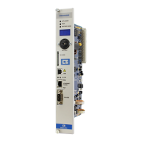
Details the components and indicators on the Classic controller's front panel.
Details the components and indicators on the Compact controller's front panel.
Explains operational status LEDs, displays, ports, and indicators.
Compares features of different CTI 2500 controller models.
Details planning considerations, including safety and electrical interference.
Provides instructions for unpacking the controller safely and properly.
Explains the location and function of user switches and jumpers for configuration.
Guides on physically mounting the controller into its base or rack.
Describes initial power-on, IP parameter setting, and automatic assignment.
Introduces the controller's programming methods.
Details Relay Ladder Logic instructions and their categories.
Explains Special Function programs and subroutines, their capabilities, and instruction groups.
Details analog loop functions, PID algorithms, and alarm configuration.
Explains how the controller stores and updates I/O data and registers.
Covers compatibility with CTI and Siemens 505/500 series I/O modules.
Covers Profibus DP I/O support, RBCs, slave devices, and data rates.
Describes the controller's various memory types and their purposes.
Explains battery-backed RAM and flash memory for user programs.
Explains high-speed DRAM for executing firmware and user programs.
Introduces the controller scan cycle and its divisions.
Details fixed, variable, and variable-with-upper-limit scan types and modes.
Explains serial port and USB port usage, driver installation, and warnings.
Details Ethernet port capabilities, IP assignment, and static IP setup.
Introduces software-initiated restart options for known states.
Provides a table detailing PLC states after different restart types.
Explains using LED indicators, event logs, and system status words.
Covers startup errors, fatal errors, and non-fatal errors with causes and resolutions.
Lists and describes various fatal error codes and their corrections.
Introduces firmware updates for corrections and new features.
Details the procedure for updating firmware via serial or USB ports.
Explains how to update firmware using an SD card.
Lists status codes and error codes during the firmware update process.
Introduces on-board flash memory for user program storage.
Details flash memory operations and restrictions when used as a program source.
Lists startup error numbers, descriptions, and corrective actions.
Lists fatal error codes, descriptions, and corrections.
Lists task code errors returned in a task code 00 reply.
Describes bits in STW 1 for status and STW 2 for base controller status.
Describes status of DP channel slaves for each slave.
Describes I/O module status for local and remote bases.
Lists analog non-fatal errors like loops overrunning or queues full.
Lists user program error codes associated with STW1 bit 6.
Indicates the status of Profibus I/O and DP bus.
Indicates additional controller status and error flags.
Explains IP address structure, notation, classes, and usage.
Explains subnet masks, CIDR notation, and how to select IP addresses.
Guides on how to replace the controller's lithium battery safely.
Lists module size, power, temperature, humidity, and battery specs.
Details the pin connections for serial, I/O, and Profibus ports.
Specifies SD/SDHC card requirements for Classic and Compact controllers.
Details acceptable SD card capacity, size, and speed for updates.
Outlines warranty period, remedies, exclusions, and disclaimers.
Details the process for requesting an RMA and returning equipment for repair.
| Ethernet Ports | 2 x 10/100/1000 Mbps |
|---|---|
| USB Ports | 2 x USB 2.0 |
| Protocols | Modbus TCP |
| SD Card Slot | 1 x microSD |
| Power Supply | 24 V DC |