2500 Series® Compact System
Control Technology Inc.
5734 Middlebrook Pike, Knoxville, TN 37921-5914
Phone: +1.865.584.0440 Fax: +1.865.584.5720
www.controltechnology.com
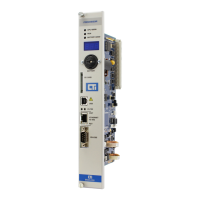
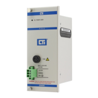
2500C-PS-24V-35 24VDC 35 Watt Power Supply
Warning:
Disable all power to the base before in-
stalling or removing the power supply. Fail-
ure to do so could cause damage to the
equipment or injury to personnel.
2500C Compact Power
Supplies are always locat-
ed in the left most slot
Caution:
Do not attempt to operate the 2500C-PS-
24V-35 out of the Voltage Operating Rang-
es specified. Damage to the Power Supply
could occur if out of range power input is
applied.
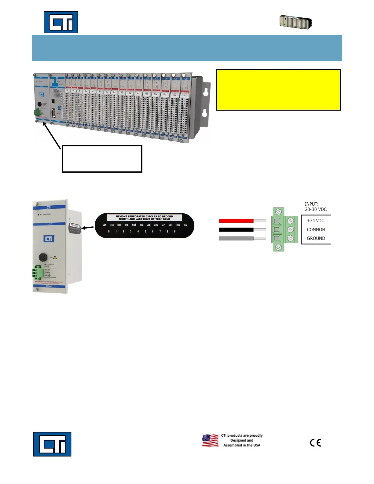
Installing Power Wiring
Use the following steps for installing and removing the 2500C-PS-24V-35 Power Supply from the 2500C Chassis.
1. Position the power supply so that the bezel is facing you.
2. Grasp the top and bottom of the power supply.
3. Carefully slide the power supply into the left most slot in the base until it engages into the backplane connector.
4. Strip power wiring back, insert the wire into the wiring connector as shown above, then tighten screws.
5. Check to make sure the power input wires are securely inserted and the fastened in the wiring connector.
6. Insert and tighten down the 3 pin removable wiring connector.
7. Be sure to tighten the top and bottom bezel screws completely.
8. Once all the chassis modules including controllers and IO are inserted then you may apply power to the power supply
inputs.
To remove the power supply, remove power from the power input by removing the power wiring connector or turning off the
power source, loosen the bezel screws, and pull the power supply forward out of the chassis until it clears the chassis.
Copyright© 2022 Control Technology Inc All Rights Reserved 17 January 2022
Note: This label is found on the side
of the power supply. It provides the
user a way to record the date the
power supply was put in service.
Please visit our website for more
User Supplied Power Input Wiring Diagram
Note: Use Copper Cunductors Only.
 Loading...