maintained. If the cutting edge of a blade has
been sharpened to within 5/8 inch of the wind
wing radius (see Figure 63), it is recommended
that new blades be installed. New blades are
available at your authorized dealer.
WIND
WING 5/8" FROM
RADIUS
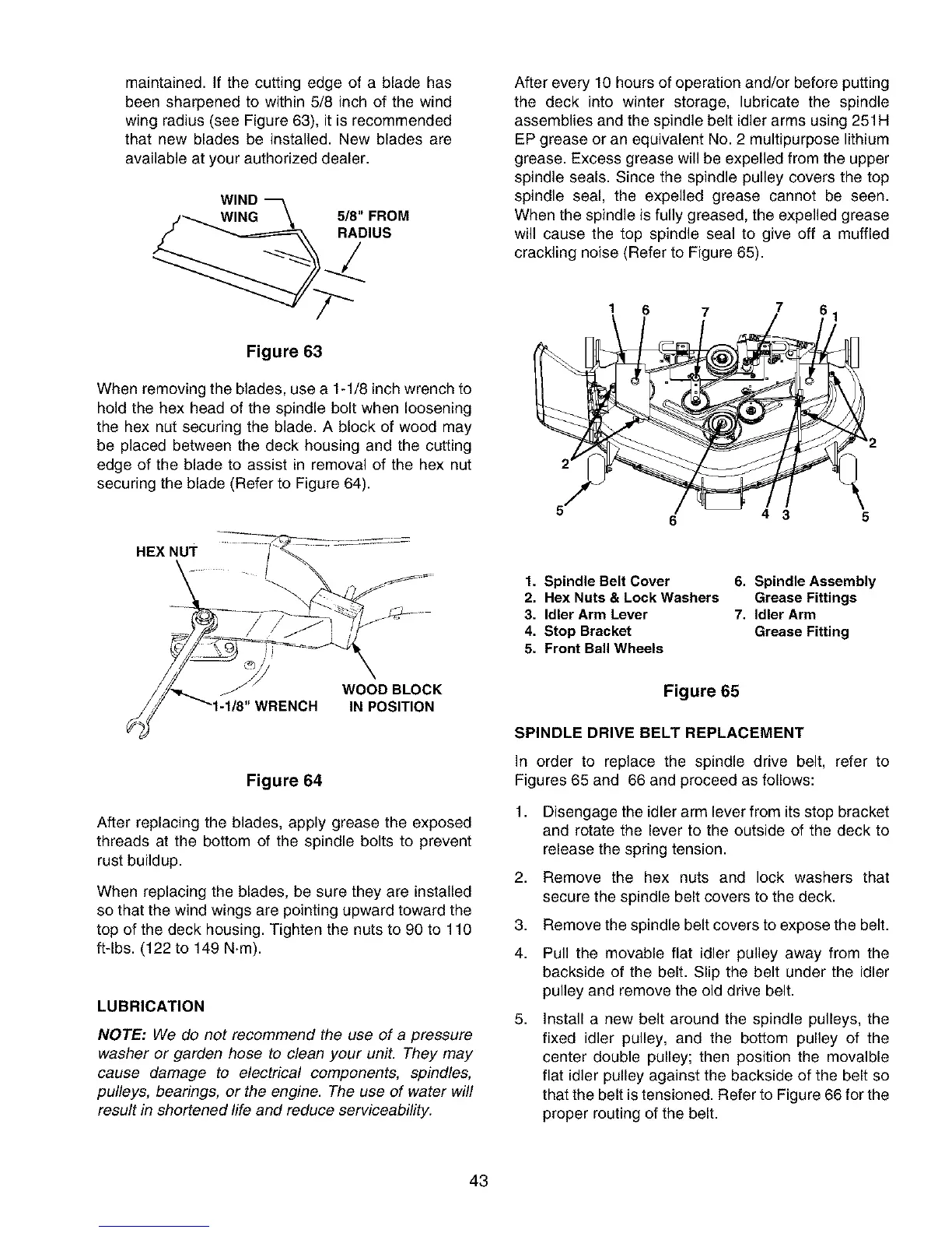
After every 10 hours of operation and/or before putting
the deck into winter storage, lubricate the spindle
assemblies and the spindle belt idler arms using 251H
EP grease or an equivalent No. 2 multipurpose lithium
grease. Excess grease will be expelled from the upper
spindle seals. Since the spindle pulley covers the top
spindle seal, the expelled grease cannot be seen.
When the spindle is fully greased, the expelled grease
will cause the top spindle seal to give off a muffled
crackling noise (Refer to Figure 65).
Figure 63
When removing the blades, use a 1-1/8 inch wrench to
hold the hex head of the spindle bolt when loosening
the hex nut securing the blade. A block of wood may
be placed between the deck housing and the cutting
edge of the blade to assist in removal of the hex nut
securing the blade (Refer to Figure 64).
HEX NUT
1 6
'2
1. Spindle Belt Cover
2. Hex Nuts & Lock Washers
3. Idler Arm Lever
4. Stop Bracket
5. Front Ball Wheels
6. Spindle Assembly
Grease Fittings
7. Idler Arm
Grease Fitting
WOOD BLOCK
1/8"WRENCH IN POSITION
Figure 64
After replacing the blades, apply grease the exposed
threads at the bottom of the spindle bolts to prevent
rust buildup.
When replacing the blades, be sure they are installed
so that the wind wings are pointing upward toward the
top of the deck housing. Tighten the nuts to 90 to 110
ft-lbs. (122 to 149 N.m).
LUBRICATION
NOTE: We de not recommend the use of a pressure
washer or garden hose to clean your unit. They may
cause damage to electrical components, spindles,
pulleys, bearings, or the engine. The use of water will
result in shortened life and reduce serviceability.
Figure 65
SPINDLE DRIVE BELT REPLACEMENT
In order to replace the spindle drive belt, refer to
Figures 65 and 66 and proceed as follows:
1. Disengage the idler arm lever from its stop bracket
and rotate the lever to the outside of the deck to
release the spring tension.
2. Remove the hex nuts and lock washers that
secure the spindle belt covers to the deck.
3. Remove the spindle belt covers to expose the belt.
4. Pull the movable flat idler pulley away from the
backside of the belt. Slip the belt under the idler
pulley and remove the old drive belt.
5,
Install a new belt around the spindle pulleys, the
fixed idler pulley, and the bottom pulley of the
center double pulley; then position the movalble
flat idler pulley against the backside of the belt so
that the belt is tensioned. Refer to Figure 66 for the
proper routing of the belt.
43
 Loading...