Throttle Control
The throttle control is located on the rear of the engine. It
regulates the speed of the engine and will shut off the engine
when moved into the STOP position.
Primer
Pressing the primer forces fuel directly
into the engine’s carburetor to aid in cold-
weather starting.
Oil Fill
Engine oil level can be checked and oil added through the oil fill.
Oil Drain
Engine oil can be drained through the oil drain.
Muffler
Engine exhaust exists the engine via the muffler.
Skid Shoes
Position the skid shoes based on surface conditions. Adjust
upward for hard-packed snow. Adjust downward when
operating on gravel or crushed rock surfaces.
Electric Starter Outlet
Requires the use of a three-prong outdoor extension cord and a
120V power source/wall outlet.
Recoil Starter Handle
This handle is used to manually start the engine.
Electric Starter Button
Pressing the electric starter button engages the engine’s electric
starter when plugged into a 120V power source.
Augers
When engaged, the augers rotate and draw snow into the auger
housing.
Chute Assembly
Snow drawn into the auger housing is discharged out the chute
assembly.
Gas Cap
Unthread the gas cap to add gasoline to the fuel tank.
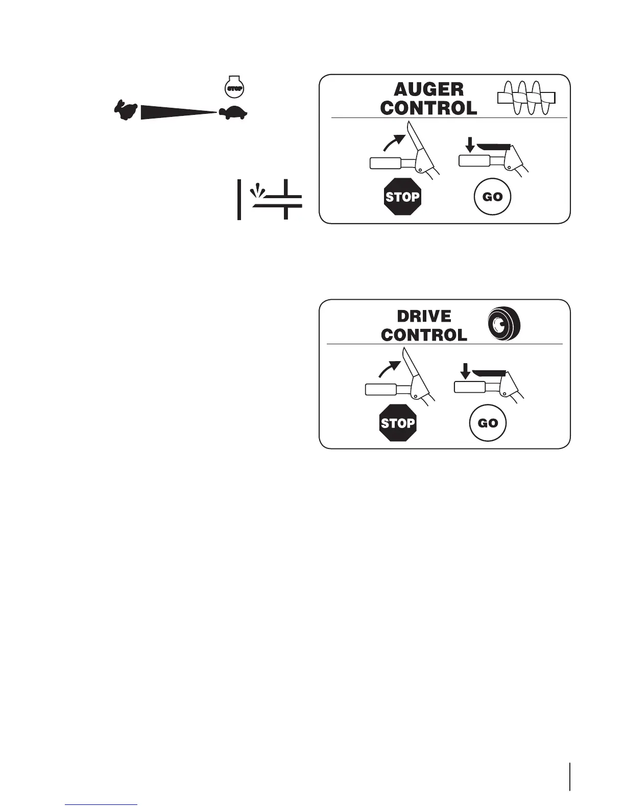
Auger Control
The auger control is located on the left handle. Squeeze the
control grip against the handle to engage the augers and start
snow throwing action. Release to stop.
Drive Control / Auger Clutch Lock
The drive control is located on the right handle. Squeeze the
control grip against the handle to engage the wheel drive.
Release to stop.
The drive control also locks the auger control so that you can
operate the chute directional control without interrupting
the snow throwing process. If the auger control is engaged
simultaneously with the drive control, the operator can release
the auger control (on the left handle) and the augers will remain
engaged. Release both controls to stop the augers and wheel
drive.
Note: Always release the drive control before changing speeds.
Failure to do so will result in increased wear on your machine’s
drive system.
11sectiOn 4 — cOntrOls and features
 Loading...