8 Section 3— controlS and FeatureS
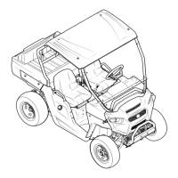
Parking Brake Lever
The parking brake lever is located between the
driver and passenger’s seat. It holds the parking
brake in the engaged position, once engaged.
To engage the parking brake, pull up on the parking
brake lever, and the parking brake indicator on
the instrument cluster will illuminate and the gear
position indicator will flash to remind you the
parking brake is engaged. See Figure 3-2.
To release the parking brake, push down on the
brake pedal, pull slightly up on the parking brake
lever while depressing button, and move the lever
to the disengaged position. The parking brake
indicator will go out and the gear position indicator
will stop flashing. See Figure 3-4.
Figure 3-4
Seat Belts
The seat belts are located on the outside of the
driver and passenger seats. Pull across your chest
and lap and secure it to the seat belt latch located
near the center console.
NOTE: Seat belt warning indicator will flash for 8
seconds once the key is turned to the ON position to
remind the operator and passenger to fasten their
seat belt.
WARNING: Always wear the seat belt
when operating the utility vehicle.
The position of the lap belt portion of the seat belt
should be positioned for both the operator and the
passenger before driving. See Figure 3-5.
Figure 3-5
Seat Belt Warning Indicator
The seat belt warning indicator located in the
instrument cluster will flash for 8 seconds once the key
is turned to the ON position to remind the operator
and passenger to fasten their seat belt. See Figure 3-2.
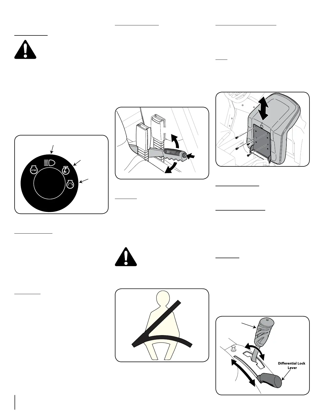
Seats
The seats can be adjusted to either the forward or
rearward position by removing the (4) bolts securing
them to the seat pan and reinstalling them into the
seat in the other (4) holes of the seat pan. Tighten
bolts to 170 in-lb. See Figure 3-6.
Figure 3-6
Bed Tie-Down Rings
The bed tie-down rings can be used to secure items
for transporting.
Differential Lock Lever
The differential lock lever is located in the center
console between the seats. When engaged, the
differential lever locks the rear differential, giving
equal power to both rear wheels. See Figure 3-7. In
addition, when the differential lock lever is in the ON
position, the Differential Lock Indicator located in
the instrument cluster will illuminate. See Figure 3-2.
Shift Lever
The shift lever is located in the center console
between the seats and has three positions
(FORWARD, NEUTRAL, and REVERSE). See Figure
3-7. The brake pedal must be fully depressed
when moving the shift lever. One of the three gear
positions will be displayed in the instrument cluster.
See Figure 3-2.
IMPORTANT: Never force the shift lever or attempt
to shift while in motion. Doing so may result in
serious damage to the utility vehicle’s transmission.
Forward
Reverse
Neutral
OFF
ON
Shift Lever
Figure 3-7
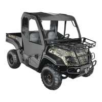
Ignition Switch
WARNING: Never leave a running
machine unattended. Always set
parking brake, stop engine and
remove key to prevent unintended
starting.
The ignition switch is located to the right of the
steering wheel. To start the engine, insert the
key into the ignition switch and turn clockwise
to the START position. Release the key into the
RUN position once engine has started. To use
the highbeam feature, turn the key back to the
highbeam position. The high beam indicator in the
instrument cluster will illuminate. See Figure 3-2 &
Figure 3-3.
Refer to Starting Engine in the Operation Section of
this manual for detailed starting instructions.
High Beam
Position
RUN
Position
START
Position
Figure 3-3
Accelerator Pedal
The accelerator pedal is located to the right of the
brake pedal, beneath the dash panel. See Figure
3-1. Depressing the accelerator pedal will move the
vehicle in the direction selected on the shift lever. As
the pedal is slowly depressed, speed will continue
to increase to the desired speed. Releasing the
pedal will reduce the speed, but will not completely
stop the vehicle. The brake must be applied to stop
vehicle.
Brake Pedal
The brake pedal is located to the left of the
accelerator pedal, beneath the dash panel. See
Figure 3-1. Remove foot from accelerator pedal and
apply pressure to the brake pedal until vehicle slows
down and stops.
 Loading...