11Section 2 — ASSembly & Set-Up
Seat Adjustment
Proper steering column and seat adjustment will
result in the following (to adjust the seat see below):
In the neutral position with hands on the steering
wheel,
• Operator’s upper arms should be relaxed
and approximately vertical.
• Operator’s forearms should be
approximately horizontal.
• Operator’s back should stay in contact with
the seat back.
• Steering column should not contact
operator’s legs.
Check the results of any adjustments to the
conditions described above. Repeat any
adjustment procedures as required until all
conditions are met.
This machine is equipped with an adjustable seat,
which includes a retractable seat belt assembly and
an Operator Presence Sensor (OPS). The OPS in the
form of a switch, is integrated into the seat bottom
and is connected to the machine electrical system.
The Operator Presence Sensor must be connected
to the electrical wiring harness.
The seat can be adjusted forward and backward,
the armrests can be adjusted up and down (700
and 900 series) , the mechanical suspension
mechanism weight/ride adjustment controls
can be adjusted for weights between 125- and
275-pounds (500 and 700 series) or air ride
adjustment (900 series), a lumbar support can
be adjusted and the seat can tilt forward and
backward.
NOTE: The seat base must be secured by the latch,
otherwise, the seat assembly could tilt forward.
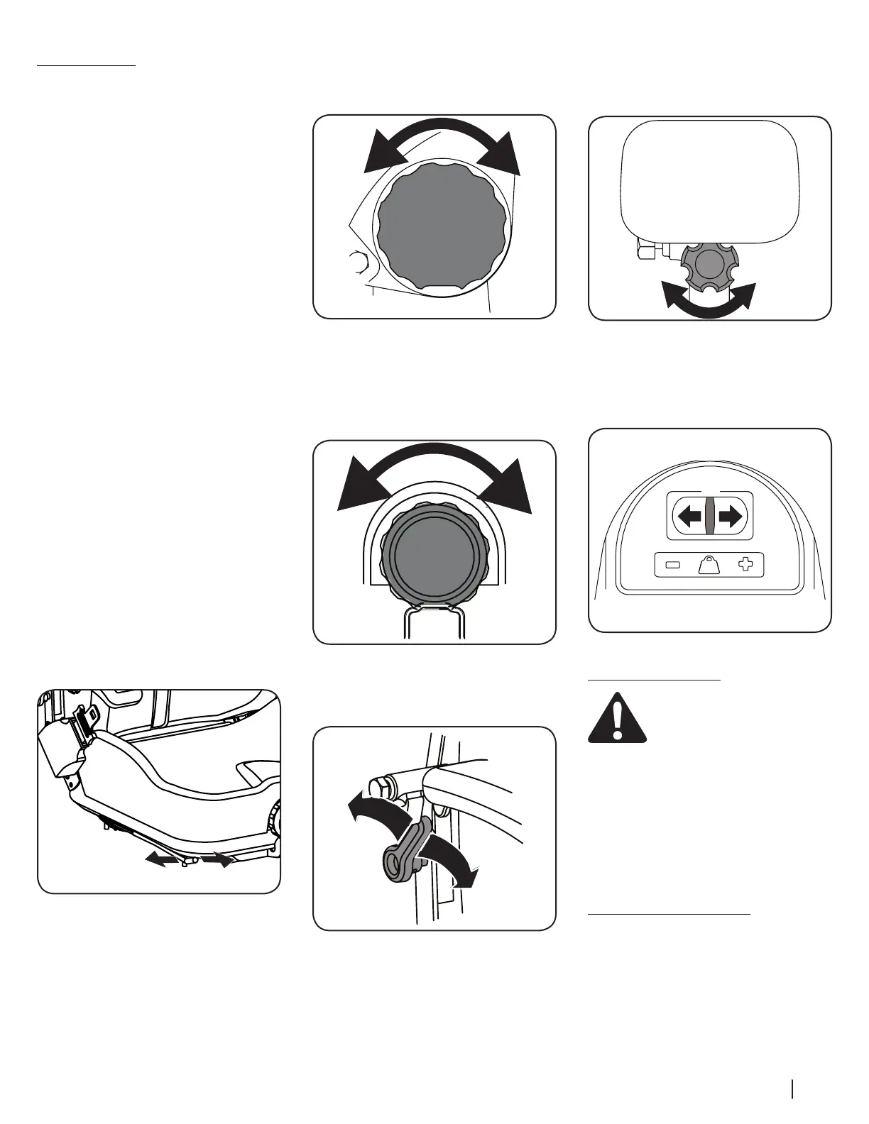
To move the seat forward or back, locate the seat
adjustment rod under the seat. Push the rod (a) to
the left and slide the seat forward or back into the
desired position and release the rod (a) when the
seat is in the desired position. See Figure 2-12.
Figure 2-12
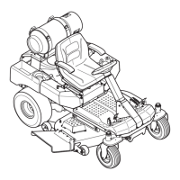
The seat tilt is controlled by the knob on the left
of the seat. Turn the knob rearward to tilt the
seat back, turn the knob forward to tilt the seat
forward. See Figure 2-10.
Figure 2-13
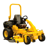
The mechanical suspension mechanism (500 and
700 series) incorporates weight/ride adjustment
controls for operators in the 100 to 280 lb. weight
range. Turn the knob on the front of the seat
clockwise to increase the weight capacity and
counter-clockwise to decrease. See Figure 2-11.
Figure 2-14
To vary the lumbar support (700 and 900 series)
move the lever on the right of the seat up and
down. See Figure 2-12.
Figure 2-15
To adjust the height of the arm rests (700 and 900
series) , lift the arm rest and rotate the knob under
the arm rest right or left to increase or decrease the
height. See Figure 2-13.
Figure 2-16
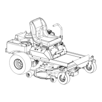
The air ride (900 series) can be adusted up or down
using the height adjustment lever on the front
of the seat. Press the lever to the left (+) to raise
the height of seat and to the right (-) to lower the
height of the seat. See Figure 2-14.
Figure 2-17
Checking Tire Pressure
Warning! Maximum tire pressure
under any circumstances is 12 psi on
rear tires and 25 psi on front tires.
Equal tire pressure should be
maintained at all times.
Inflation Pressure
Rear Tires — 10-12 psi max
Front Tires — 20-25 psi max
The tires on your tractor may be over-inflated for
shipping purposes. Reduce the tire pressure before
operating the tractor. Recommended operating
tire pressure is 10-12 psi on rear tires and 20-25 psi
on front tires.
Lubrication & Grease Points
Before operating the tractor, refer to the Service
section of this manual to check the lubrication and
grease points. Grease and lubricate if necessary.
 Loading...