Do you have a question about the Curtis Dyna-Fog CyClone 2730 and is the answer not in the manual?
Details the electric "Cold Fog" ULV machine, its aluminum nozzle, polyethylene body, and applications.
Lists Cyclone models 2730/2732 voltage, blower continuous duty, voltage, amperage, frequency, RPM, and CFM.
States the machine is a high-quality ULV/Mist generator and proper maintenance ensures longevity.
Covers electrical hazards, grounding requirements, proper extension cord use, and workspace conditions.
Explains how formulations can be combustible and the risk of propagating flame from fine particles.
Defines acceptable aerosol limits and advises eliminating ignition sources to prevent fire or explosion.
Outlines essential "DO" actions like reading the manual and "DO NOT" actions like spraying flammable liquids near ignition sources.
Describes the motor, blower, nozzle, formulation injection, and droplet formation process.
Explains how air and liquid are combined to form mist, and how the formulation tank is pressurized.
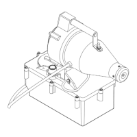
Identifies main parts of the Cyclone machine, including nozzle, blower housing, formulation tank, and metering valve.
Details 7 steps for proper formulation application, from determining rate to applying for the calculated time.
Guides on reading labels, measuring enclosed volume, calculating amount required, and using the flowability meter.
Explains how to use the flowability meter to measure liquid drain time and determine flow rates.
Details using tables to find application time based on amount required and machine flow rate.
Outlines the sequence of operations for applying formulation, including setting valve, plugging in, and turning on.
Covers cleaning the formulation tank, electric cord inspection, blower motor checks, and air intake filter cleaning.
Provides a step-by-step guide for adjusting the metering valve gland nut tightness for optimal performance.
Details the unit's weight (14.2 lbs/6.4 kg) and formulation tank capacity (1 US Gallon/3.8 L).
Explains how to adjust the machine's angle from horizontal to 20° below horizontal using the locking handle.
Describes how rotating the metering valve knob adjusts flow rate and references Table 1 for settings.
Clarifies that Table 1 flow rates are for water and thicker liquids may differ, advising calibration.
States the device dispenses spray/mist and formulations may require government registration or approval.
Explains how to use Table 2 to determine the formulation amount needed based on space volume and application rate.
Explains how to use Table 3 to find the application time based on required ounces and machine flow rate.
Warns that fan replacement should be done by a certified representative due to high blower speeds.
Explains fan material deterioration in closed rooms and recommends a Fresh Air Intake Hose.
Provides detailed steps for disassembling the blower assembly to access and replace the rotary fan.
| Model | CyClone 2730 |
|---|---|
| Manufacturer | Curtis Dyna-Fog |
| Flow Rate | Adjustable |
| Fluid Capacity | 5.7 liters (1.5 gallons) |
| Particle Size | 5-30 microns |
| Heater Wattage | Not applicable |