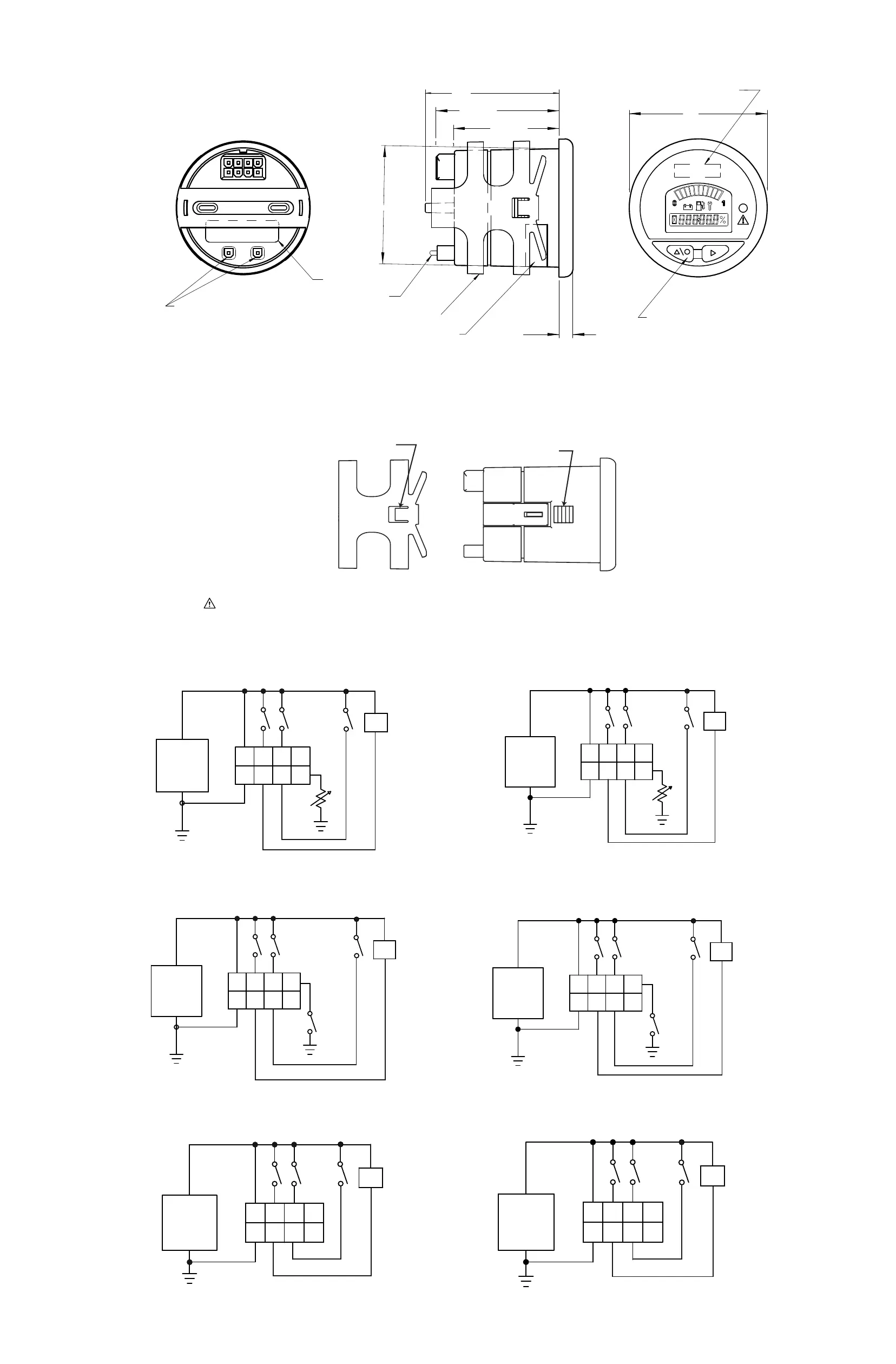
DO NOT CONNECT WHEN INSTALLING GAUGE
USED FOR DEVICE CONFIGURATION
8
4
5
1
LABEL
LABEL
SEAL
MOUNTING BRACKET
51.5 MAX
46.0 MAX
53.6 MAX
58.5
6.3
MEMBRANE SWITCH USED
FOR FUNCTIONALITY SETUP
OF GAUGE
60.0
LOGO AREA/SCALES
AS REQUIRED
4.0 This unit is designed for a mounting panel thickness of 0.8mm - 6.4mm.
Cover, Overlay & Mounting Bracket- Polycarbonate.
3.0 Material: Case- Polycarbonate; Lens- clear Polymethylmethacrylat (pmma);
Rating 94V-0, pins P/N 39-00-0039 for #18-24 AWG
1.0 Mating Connector: 8-pin Molex P/N 39-01-2085 with UL-
NOTES:
2.0 52mm meters are provided in a standard round package for
mounting in a 52mm DIA dash panel hole. See detail for panel cutout with key.
5.0 Environmental protection: Front- IP-65; Rear- IP-40.
6.0 Weight: 0.095 kg max, including mounting bracket.
SUPPLY
12
3
4
5
678
HOUR METER
ENABLE
SETUP
ENABLE
RESISTANCE BASED SENDER
+
-
SUPPLY
AUTO-RANGE SWITCH
OPEN = 24 or 48
CLOSED = 12 or 36
+
-
SUPPLY
KEYSWITCH
V+
V-
PIN 7 = 0.5A FET
HOUR METER
ENABLE
SETUP
ENABLE
KEYSWITCH
V+
V-
PIN 7 = 0.5A FET
HOUR METER
ENABLE
SETUP
ENABLE
KEYSWITCH
V+
V-
PIN 7 = 0.5A FET
LOAD
*
SUPPLY
123
4
5
678
RESISTANCE BASED SENDER
+
-
SUPPLY
123
4
5
678
AUTO-RANGE SWITCH
OPEN = 24 or 48
CLOSED = 12 or 36
+
-
SUPPLY
123
4
5
678
+
-
HOUR METER
ENABLE
SETUP
ENABLE
KEYSWITCH
V+
V-
PIN 3 = 0.5A FET
HOUR METER
ENABLE
SETUP
ENABLE
KEYSWITCH
V+
V-
PIN 3 = 0.5A FET
HOUR METER
ENABLE
SETUP
ENABLE
KEYSWITCH
V+
V-
PIN 3 = 0.5A FET
LOAD
*
SUPPLY
12
3
4
5
678
HOUR METER
ENABLE
SETUP
ENABLE
RESISTANCE BASED SENDER
+
-
SUPPLY
AUTO-RANGE SWITCH
OPEN = 24 or 48
CLOSED = 12 or 36
+
-
12
3
4
5
678
12
3
4
5
678
V+
V-
PIN 7 = 0.5A FET
HOUR METER
ENABLE
SETUP
ENABLE
KEYSWITCH
V+
V-
PIN 7 = 0.5A FET
HOUR METER
ENABLE
SETUP
ENABLE
KEYSWITCH
V+
V-
PIN 7 = 0.5A FET
LOAD
*
LOAD
*
SUPPLY
123
4
5
678
RESISTANCE BASED SENDER
+
-
SUPPLY
123
4
5
678
AUTO-RANGE SWITCH
OPEN = 24 or 48
CLOSED = 12 or 36
+
-
SUPPLY
123
4
5
678
+
-
HOUR METER
ENABLE
SETUP
ENABLE
KEYSWITCH
V+
V-
PIN 3 = 0.5A FET
HOUR METER
ENABLE
SETUP
ENABLE
KEYSWITCH
V+
V-
PIN 3 = 0.5A FET
HOUR METER
ENABLE
SETUP
ENABLE
KEYSWITCH
V+
V-
PIN 3 = 0.5A FET
LOAD
*
LOAD
*
SUPPLY
12
3
4
5
678
HOUR METER
ENABLE
SETUP
ENABLE
RESISTANCE BASED SENDER
+
-
SUPPLY
AUTO-RANGE SWITCH
OPEN = 24 or 48
CLOSED = 12 or 36
+
-
SUPPLY
+
-
12
3
4
5
678
V+
V-
PIN 7 = 0.5A FET
HOUR METER
ENABLE
SETUP
ENABLE
KEYSWITCH
V+
V-
PIN 7 = 0.5A FET
HOUR METER
ENABLE
SETUP
ENABLE
KEYSWITCH
V+
V-
PIN 7 = 0.5A FET
LOAD
*
SUPPLY
123
4
5
678
RESISTANCE BASED SENDER
+
-
SUPPLY
123
4
5
678
AUTO-RANGE SWITCH
OPEN = 24 or 48
CLOSED = 12 or 36
+
-
SUPPLY
123
4
5
678
+
-
HOUR METER
ENABLE
SETUP
ENABLE
KEYSWITCH
V+
V-
PIN 3 = 0.5A FET
HOUR METER
ENABLE
SETUP
ENABLE
KEYSWITCH
V+
V-
PIN 3 = 0.5A FET
HOUR METER
ENABLE
SETUP
ENABLE
KEYSWITCH
V+
V-
PIN 3 = 0.5A FET
LOAD
*
AMP ConnectorMolex Connector
Resistive based sender input (i.e. temp, fuel and pressure).
BDI (with auto- range switch)
Voltmeter
2.2 Typical Wiring Diagrams
2.3 Mounting/Dimension Drawing
LOCKING TAB MUST ALIGN WITH LOCKING SERRATIONS
LOCKING TAB
LOCKING SERRATIONS
*
Use of output FET driver requires installation of suppression diodes across all inductive loads.
Information is for standard design units only. Customers should review
specific diagrams for custom units.
Information is for standard design units only. Customers should review
specific diagrams for custom units.
 Loading...